System Development Activities

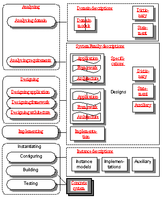
The following overview of TIMe is structured according to system development activities, and the corresponding kinds of models and descriptions are introduced along with the activities. In this overview emphasis is put on the activities leading to implementation.
This chapter covers the following activities:
- "Analysis"
- "Design"
- "Implementation"
- "Instantiation"
Domain Statement: what is it all about
Domain object model: modeling the established domain concepts
Dictionary: not just a data dictionary
Framework/Infrastructure specification
Application Design: where the real functionality is designed
Architecture Design: choice of implementation platform
Framework Design: from Infrastructure to Framework
Guidelines on Object and Property Modeling are provided in a separate chapter ( "Object and Property Models - and the Languages for describing them"). These are modeling techniques that are part of many activities and therefore most conveniently covered in one place. That chapter includes guidelines on the matching of properties and objects, and on the transition from UML to SDL object models.
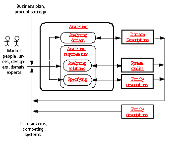
The objectives of analysis are to understand the domain and what users and other stake holders want to achieve, i.e. their needs, to find improvements to existing systems, or to plan new product families that will give valuable improvement and thus create business in the future.
Product Planning
Product planning is another word for analysis. Product planning is a strategic process at the company level. Its main goal is to consider needs existing in the market and plan new products or enhancement to existing products. Few tasks are more critical to the success of a company than its product planning. Product development is a process which produces the new products or product enhancements that are planned.
Why domain descriptions?
At the product planning level, domain descriptions are used to collect and organize domain knowledge in a way that will enable product development to work more efficiently.
At the product level, product families will enable faster and more cost effective configuration and production of system instances, while common components will be used to develop product families more efficiently.
Product planning consists of two main activities: Domain analysis and requirements analysis. The task of the latter is to plan what parts of a domain to support by a new system family and to specify its required properties.
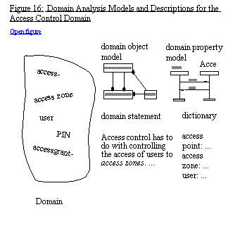
The first analysis will be an analysis of the domain. This includes identifying which phenomena and concepts (like access zones, access points) are part of the domain, with focus on concepts. The result is represented by two domain models:
Domain object model in UML
- A domain object model, that is a collection of classes with attributes, relations and communication connections that describe the general concepts of the domain, without going into details needed for design and implementation.
UML is the main notation used for this kind of modeling, but if it for some reason should be important to describe some general states and transitions, then SDL is used.
Domain property model in MSC
- A domain property model, that is a description of properties of domain object classes, and of roles.
Domain objects do not have to be just "data (passive) objects", so properties may involve interaction properties - they are described using MSC. Other kinds of properties are described using natural text, e.g. organised in lists of required properties. If interaction properties are not obviously associated with objects from the domain object model, we will say that they are associated with roles.
Dictionary
- A dictionary, that is a list of terms with an explanation of their meaning, including each of the elements of the domain object model. A dictionary is not just a data dictionary, it also includes definitions of concepts that exhibit behaviour.
Domain statement
- A domain statement, that is a concise description of the domain with focus on stake holders and their needs, the essential concepts, functions and work processes, rules and principles.
It is normally sufficient to express the domain statement informally using natural language and drawings, but one should try to be as clear and precise as possible.
These models and descriptions represent the understanding of the domain common to users, owners and developers of systems in the domain, see Figure 16.
Domain Statement: what is it all about
The domain statement leads to the very first understanding of what the domain is all about. It helps to clarify needs and to understand the real purpose of systems in the domain. It also serves as an introduction to the other domain descriptions.
The domain statement can often be based on existing prose descriptions. There may be descriptions of earlier systems, there may be textbooks on the subject and there may be informal statements about the system.
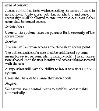
Domain Statement
By considering similar systems on the market, by analysing the needs and by consulting domain and market experts, the short Domain Statement V1 is written. It seeks to describe what is special for this domain in contrast to other domains, and is used to guide what to include and not in systems.
Domain object model: modeling the established domain concepts
Classes and objects
A domain object model describes the domain from an object oriented perspective. It defines classes which represent concepts in the domain, and objects which represent phenomena in the domain. It defines the attributes, the operations and the behaviour of objects as well as associations and communication connections between objects.
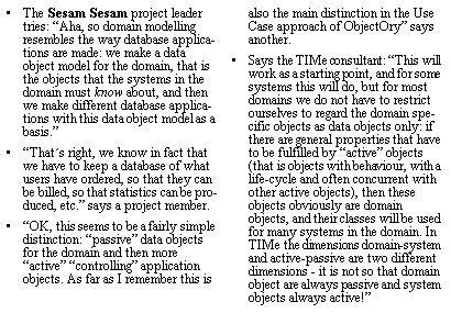
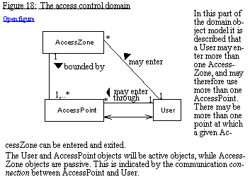
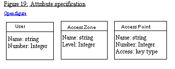
With this definition of domain object model, it is rather straight forward to identify the domain specific objects. In our example it turned out that some of these were really "active objects" (e.g. User and AccessPoint in Figure 18). Note that this object model comes about when considering only classes, relations and connections. If only considering e.g Use Cases, AccessPoint may not have turned up, but rather a role like AccessGranting.
Dictionary: not just a data dictionary
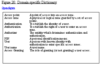
The objective of the dictionary is to define terminology and thereby enable precision in communication between people involved. Terminology names the domain specific concepts and defines their meaning.
An important set of concepts in the dictionary is the set of concepts that are covered by the corresponding domain object model. There may also be phenomena, like e.g. access granting, that will not be covered directly by a class in the object model, but by property models involving more than one class of objects.
It is important that not only "data" concepts are included in the dictionary, but that typical "event"- or "action" concepts also are included - hence the name Dictionary and not Data Dictionary.
Domain property model: modeling the needs
A Domain Property Model is used to describe the problem domain from the Property perspective. It includes functional and non-functional properties.
Functional properties are considered as projections of object behaviour, and are described using text, role structures and MSC.
Important properties for the systems that TIMe is intended for are properties of interaction between parts of the systems and parts of the environment. Some methods recommend pure role modeling for this purpose: that is all instances involved in interaction scenarios are roles played by some objects that will be found during design. Other methods (like UML) use the object model as the basis for interaction scenarios, and therefore only have objects as instances in interaction scenarios, never roles.
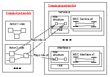
TIMe supports a mixture: if interaction properties are obviously associated with objects already identified in the object model, then the property models describe the properties of these. On the other hand, if the object model has not even been identified, it is still possible to make interaction scenarios only involving roles. During design, roles will be assigned to objects. The relationships between objects and properties are illustrated in Figure 21.
Role structures
Text is used to give a textual explanation of a service or interface. Role structures are UML instance diagrams that represent the roles of the service or the interface. The objects in role structure diagrams can be considered as anonymous objects. They will be related to object model objects by role association links, and to the instances in the service MSCs through the same name.
When the system is designed, the domain property models will also be valid property models of the corresponding (domain given) system objects. Properties belonging to the domain will be candidates for properties of several systems in the domain.
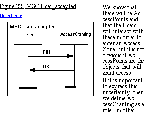
MSC does not take any stand as to what the instances are - an instance just represents one sequence of events (sending and receiving messages).
This activity produces requirement specifications in terms of context specifications in UML or SDL (depending on the desired degree of formality and on the starting point) eventually supplemented by content specification where this is known and needed in order to fully specify requirements. Corresponding property specifications are produced.
The activity will specify the properties of the systems down to a level where the system can be evaluated and compared to other possible solutions. It studies different system alternatives, and it makes requirements on how systems shall be instantiated and how they may evolve.
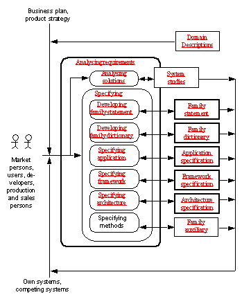
In addition it updates the Dictionary and Domain statement from the domain analysis with elements that have to do with the introduction of a specific system (or family of systems) in this domain.
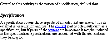
Requirements specification
A requirements specification is a document which is normally produced early in a development project and used as a contract for the design work. It will contain specifications and other items of relevance at that stage. After delivery we are interested in the provided properties (i.e. specifications) of the system, and are not interested in the historic document. TIMe unites these two aspects in the single term specification.
Specifications vs. design
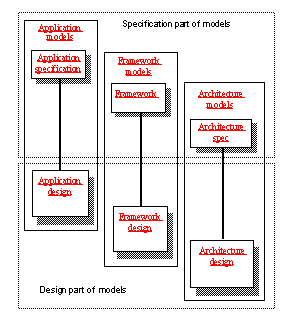
Specifications contain the specification parts of Application, Framework and Architecture models (see Figure 10:"Context/content").
Systems are part of an actual use environment
Requirements are requirements to systems. Systems within the same domain will have in common that they handle the same kinds of phenomena. All systems within the access control domain will handle access zones, access points, and users that want to get access to access zones.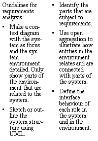
A specific system may in addition have properties that are needed because the system will have other categories of users, e.g. operators that have other requirements to the system, or an owner that e.g. wants statistics on the traffic. A specific system may also have interfaces to other systems in the environment.
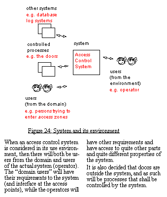
When analysing and designing a system within a given domain, the domain models will be of less use if the method does provide guidelines on how they contribute to the system design. In addition to the properties identified as part of domain analysis, there will be required properties that are specific for this system in its use environment. It is an experience that interface properties should be treated separately.
TIMe therefore has a system reference model, where these three aspects are treated as separate issues and contribute differently to the system design, see Figure 25.
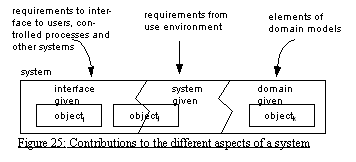
The domain models contribute to the domain given aspects of the system. These aspects will be more stable than the interface and system given aspects, and the domain given classes used for design will have a greater potential than the other classes for being (re)used in other systems in the same domain. That's the motivation for this distinction.
- UML with the system represented by a central class and connections represented by special relations, or
- SDL with the system represented by a block type with gates (see Figure 26).
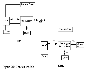
The choice depends on how close to UML one desires to be or how formal the context specification shall be. If SDL is chosen, then really only the connections can be shown, while UML can also show the relations (connections are special relations).
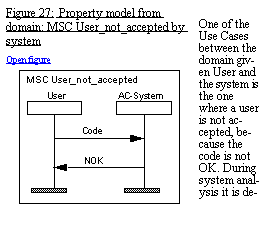
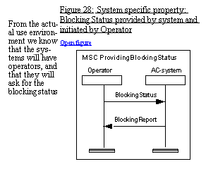
Such context models are matched with corresponding Use Cases (also called Interaction Scenarios) in MSC, where each connection corresponds to one or more MSC diagrams (see Figure 27 and Figure 28).
Requirements analysis produces a (requirements) specification for the system to be designed. It may be so that the system has an inherent structure, and that this has to specified in order to get the specification right. In that case, the specification includes a structuring of the system by means of "real aggregation", and the environment communicates with the parts of the system (see Figure 29).
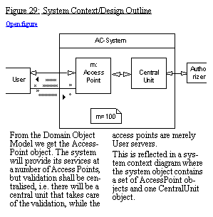
When specifications include a structuring like this, the corresponding property models must be changed correspondingly, so that User does not only interact with AC-system but with AccessPoint, and Operator not with AC-System but with CentralUnit.
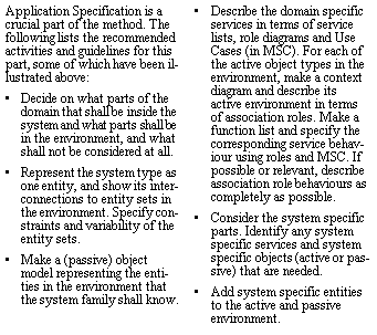
System analysis may also consider the interface specific properties and specify corresponding context/content models. When the system specification has included parts of the system (as with AccessPoint and CentralUnit in Figure 29), then the interface specification may take that into account. In Figure 30 it has been decided that the interface of AccessPoint shall be to a panel and to a door, and the corresponding objects of AccessPoint have been identified.
In addition to considering the application specific properties of a system, system analysis may also take requirements on Platform into consideration and specify these. Platform has to do with non-functional requirements to the implementation, e.g. the choice of technology, implementation principles, etc.
While the application specification is an abstract description which does not take physical aspects into account, the Implementation is considered as a concrete description. A central idea in the methodology is to describe abstract systems in a way that can be understood and validated without knowing how they are implemented.
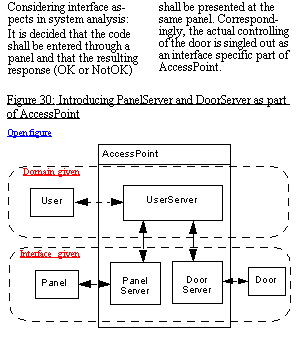
The concrete description is composed from real hardware and executable software. The concrete system will have an Application part where we find the implementation of the abstract system, and a support part containing additional functionality needed to execute the application. It will often be distributed and have additional support for internal communication, see Figure 31.
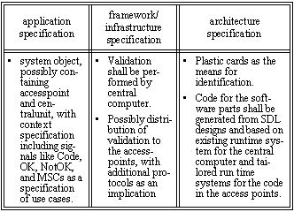
For the access control system, Architecture Specification amounts to specifying e.g. that plastic cards shall be the means for identification, and that implementation code for the software parts shall be generated from SDL designs and based on an existing runtime system.
Framework/Infrastructure specification
Consideration of issues like distribution, systems management, etc., that is behaviour that has to be part of the system but does not contribute to the services it provides, produces the Infrastructure specification.
The application Framework is an abstract system which takes into account concrete system issues such as distribution and error handling. It consists of a distributed Application part, and an Infrastructure part.
TIMe recommends developing a refined and restructured, complete functional specification reflecting the concrete system and the implementation dependent requirements, and turning this into a Framework specification, as illustrated in Figure 32.
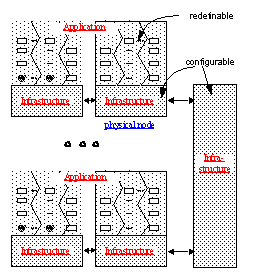
If the Infrastructure specification can be constructed so that it forms a Framework for systems with the same Infrastructure, but with varying Application part, then this is done. The application specification is changed accordingly. The idea is that if a system can be made as an instance of a Framework, with much of the general properties of the Framework isolated in the Infrastructure, then the Framework will have a potential for being reused as a design.
In "Object and Property Models - and the Languages for describing them" we illustrate the access control system where the Infrastructure and Platform issues have been considered.
For the access control system the fact that validation shall be performed by central computer is an infrastructure issue, like the possibility of distribution of validation to the access points, with additional protocols as an implication.
In an initial development the infrastructure aspect may not be obvious. Frameworks will often come as a result of a (successful) initial development, which is to be used as a basis for a new system. If e.g. distribution has been considered and isolated in an infrastructure part, the next system with the same infrastructure but with a different application part can reuse this framework.
Design object models in SDL
This activity produces design object models primarily in SDL. Some parts of the design have to do with the required properties ( Application design), another part of the design has to do with Architecture specific issues (including non-functional properties in contrast to the functional properties of application design), and a third part combines these two into a Framework for instantiation of specific systems with the same infrastructure.
Design is a creative process. One thing is that the system design model will be in SDL, while analysis models may be in UML. Another thing is that design may require a restructuring, and will certainly add details and precision.
TIMe contains guidelines on how to transform UML models into SDL models, and these are more or less automatic. It is a point, however, that they are not quite automatic - if they were there would be no need for the UML models (or for the SDL models). The interesting transformation is to take the system requirements, identify the system objects and assign attributes and behaviour to these object so that required properties are fulfilled.
Specifications contain the specification parts of Application, Framework and Architecture models. These are related to the design parts, as indicated in Figure 33.
The main design language is SDL, but in cases where the system will be a combination of SDL components and components created e.g. from an UML model, or using an interface construction tool, the main design may be in UML.
There is some help to get in this main part of design activity. As mentioned above, the system analysis produces specifications on three levels, and the system design follows these specification levels:
- "Application Design: where the real functionality is designed"
- "Framework Design: from Infrastructure to Framework"
- "Architecture Design: choice of implementation platform".
Application Design: where the real functionality is designed
Application Design produces context and content designs (in terms of structure and behaviour) for the system type and/or for types being used in the system:
Application context, that is a context model for the type, i.e. a diagram with the type as a single entity. It specifies the environment, the interfaces and the knowledge of the type as well as external types which are used as components. It also specifies the context properties, i.e. services, and describes all objects in the environment.
Application structure applies to types that consist of object aggregates, defining the content as a structure of components.
Application behaviour applies to types that have a behaviour of their own, e.g. SDL processes.
The first purpose of an application design model is to describe the system behaviour at an abstraction level, where it can be understood and analyzed independently of a particular implementation. This is done in terms of both an object and a property model.
The second purpose is to be a firm foundation for designing an optimum implementation satisfying both the functional and non-functional requirements.
Application design starts from the application context and the required properties. New objects may be introduced during design, and these are also subject to the context/content distinction.
The application content may introduce new component types. In general the component types and application types are designed in the same way:
From domain objects to design objects
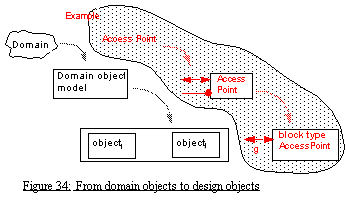
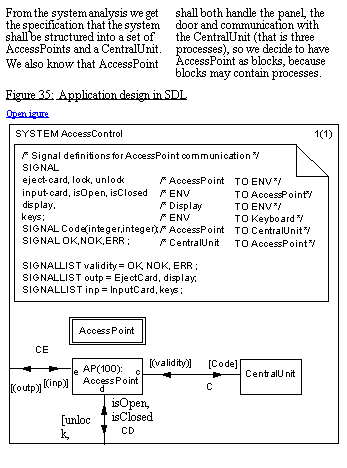
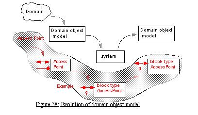
As mentioned above, some domain objects are candidates for design objects. In Figure 34 it is indicated that AccessPoint may become a block type in the SDL design.
Another source of design objects comes from mirroring the entities in the environment of the system. Considering the system specific aspects or properties will either add new classes to the set of classes from the domain object model, it will add system specific properties to domain object model classes, or it will make new subclasses to the domain model classes. This may give the application specific objects two aspects: domain given and system given. The pure domain model classes can be used in all systems in the domain, while the system specific (sub)classes can only be used in systems with properties specific for this family of systems.
Subsystems or not, and when
In some cases it is obvious that the system shall be decomposed into subsystems, or that objects in the system have a content structure. In that case this is directly supported by the SDL block concept. An SDL system simply consists of a number of blocks connected by communication paths, so-called channels, and the blocks may in turn either contain a new substructure of blocks or sets of processes.
TIMe establishes rules for good subsystem design that are readily supported by SDL. Subsystems may either come as reflecting an inherent structure of the system, as e.g. the division into central unit and a number of access points, or they may come from a pure functional decomposition.
TIMe advocates to start the subsystem decomposition from an inherent structure and then introduce new subsystems if it turns out that required properties cannot be obtained by assigning behaviour to already identified subsystems.
Inspiration from the environment
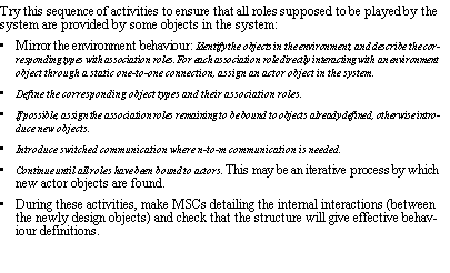
"Finding" the content objects may in some cases appear as "magic" and may require some experience from good design for similar systems. However, once the environment is well defined, the task is simpler. With a slight adaptation of an old saying: Tell me who is in your environment and I will tell you who you are (i.e. what your content is).
In addition to guidelines like this, the complete TIMe contains rules for good design in SDL (e.g. when to use concurrent processes, purpose of block substructuring, redesigning by generalisation, etc.).
Object (behaviour) design
If system content decomposition in terms of subsystems is not obvious, TIMe advocates to design the object types first. That is identify the attributes and behaviour that each object shall have in order to fulfill the required properties.
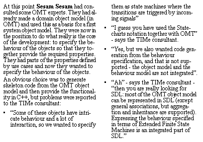
For design in SDL, object behaviour design amounts to identifying the required processes and specifying these by means of variables, procedures and behaviour in terms of states and transitions. The context design of the class leads to gate definitions in the corresponding SDL type, while the property models are input to the combined behaviour of the process.
In the object design, property models can be made more detailed and precise.
TIMe contains guidelines for how to come from a set of property models in terms of MSC to the corresponding process type in SDL. A short description of these guidelines are found in "From MSC Property Models to SDL Object Models".
In the first round it is recommended to ignore the interface specific behaviour. We know that AccessPoint will have a part that handles the user without considering how the card code and the PIN are entered via the panel (UserServer in Figure 30: "Introducing PanelServer and DoorServer as part of AccessPoint"). From the MSCs between system objects we know that this part of AccessPoint shall also handle the communication with the CentralUnit, so we rename "UserServer" to the more neutral "Controller", see Figure 36.
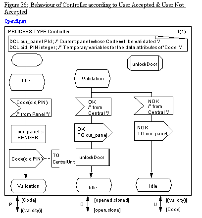

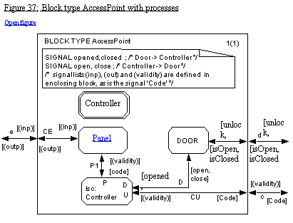
This process type fits into a design of the AccessControl object as a block (defined by a block type) as in Figure 37.
Designing non-domain given objects
Should all required properties lead to attributes and behaviour of the domain given objects? The answer is no!
The main purpose of the distinction between domain and system given aspects is that special services should not be associated with domain objects, as these will probably not be of interest to other systems in the domain. Besides working as inspirations for application objects, domain object classes are candidates for re-use in different systems in the same domain.
Which objects should then provide a property that is not obviously covered by a domain given object?
The answer is:
The last alternative requires that the domain object class is represented also in the design language, and it is recommended to document that the subclass is system given and not domain given.

If it is an interface property, and if the property has to do with the actual appearance or implementation of the interface, then it should be provided by a separate interface object, like the Panel process in Figure 37. Low-level interface (protocols) or the window part of a user interface should be isolated in special objects, while interface given behaviour at the "application" level can be provided by specialisations of domain classes. The main thing is to isolate the objects that may change with change of underlying technology. The answer can also be given by how the interface is to be provided (existing protocol implementations, user interface toolkits).
If it is a system given property and if it requires e.g. a separate computation or interaction with other non-domain given objects, then it should be provided by a separate system object. An example of this is the operator handling object. It should be defined as a separate object, but its class may e.g. be a specialization of a class that exists, e.g. AccessPoint.
It may be tempting to take each use case and make a kind of "control" object that takes care of this use case - then it will at least be easy to trace it when considering new requirements related to the use case. Most often, however, the instances in the MSC diagrams for the use cases only represent Roles or partial behaviour of some role. The challenge in design is rather to distribute the required behaviour to objects, and objects will often play several roles.
Evolution of domain models, including design issues
The distinction between domain, system and interface given aspects may change over time. The domain may be narrowed to include some of the other aspects, and the classes of the domain models may include more and more of the properties that appear to be common for many systems.
Locally defined types or types in packages?
Where shall the application given design types be defined? A priori they are defined as part of a system model.
Types may be defined in SDL packages and used by the system model. Such packages may either be system specific or more general.
Types in the latter kind of package will have to be more general than in the first kind of package, as they shall be usable in more than one system. As a starting point, design types are defined as part of the system and shall at least fulfil their "mission" there. In addition, it is recommended that types are turned into general types that can be used in other systems.
TIMe provides guidelines on how to achieve generality:
- by generalization, that is by defining supertypes with virtual properties for redefinition in subtypes, and
- by parameterization, that is types with context parameters, so that types can be fully defined without being in their actual contexts.
Even when defining a general type it is advocated to specify possible requirements on the contexts in which the type can be used. These come from the context models and are readily expressed by gate constraints in SDL types.
Architecture Design: choice of implementation platform
Architecture Design designs an implementation architecture that will behave as defined in the application object model and that satisfies the non-functional properties, taking the actual platform in terms of hardware and support software into account. It will also define a process for (automatic) generation of application implementation code and for configuration and building of system instances.
The purpose of architecture design is to answer how the system is going to be realised. This is expressed using Architecture descriptions that show:
- the overall architecture of hardware and software;
- how Frameworks and Applications are mapped to the Architecture.
While the Application and the Framework has focus on functional properties and behaviour, the Architecture has focus on non-functional properties and physical structures. The purpose is to give a unified overview over the implementation and to document the major implementation design decisions.
Architecture design determines critical architectural issues such as physical distribution, global addressing schemes and fault handling. Some of these may subsequently be reflected in the Framework model in order to describe the complete system behaviour.
The Architecture consists of two main parts:
- The Platform, which consists of the hardware with support software (such as the operating system, a DBMS and middleware) and the Infrastructure.
- The Application implementation.
Associated with the architecture it is recommended to define a process for (automatic) generation of code and for configuration and building of system instances.
Architecture design is only performed when the implementation mapping is undefined or needs to be changed. This occurs during the initial development of a system family and during maintenance when changes in the platform are made.
During normal application evolution, the Architecture will stay the same, and system evolution can take place mainly at the Application level.
Hardware and software architectures are defined to a level of detail from which implementation is well defined. The architecture shall separate between support mechanisms, such as an operating systems, and applications.
In an initial development, Architecture design will come before Framework/Infrastructure design. Architecture design involves the choice of implementation platform, what should be done in software and what in hardware, etc. The design may have to be adjusted according to this choice. SDL tools may e.g. impose restrictions in order to support code generation.
TIMe has a 5-step procedure for making architecture design. This is not applied to the example in this overview and is therefore not covered here.
Framework Design: from Infrastructure to Framework
Framework Design defines an abstract and generic framework object model and a method for instantiating the Framework with Applications. In this activity the implementation dependent functionality is taken into account, e.g. distribution support, error handling and configuration. It develops a layered approach which separates the Application and the implementation dependent Infrastructure. The infrastructure part will be nearly complete, and the rules for mapping Applications to the Framework will be well defined.
The infrastructure part of a system contains additional behaviour needed to fully understand what the system does (i.e. the complete system behaviour). Here we find objects and parts of objects that support distribution, system administration and other facilities not directly related to user services. Whenever practical the Application and the Infrastructure should be put together in a Framework that serves to simplify the definition of new systems. This implies that the objects that are mainly application specific objects will get some infrastructure specific elements in order to work on the given Infrastructure.
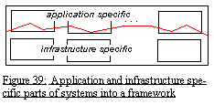 When taking infrastructure aspects into consideration, the system as designed from an application point of view may be redesigned. Restructuring does not mean that everything has to be redefined. A majority of the processes from the first application design may be left unchanged. As they are defined as stand alone types, it is a simple matter to put them into a new structural context together with some new processes.
In general it will be an advantage if the application design has been done by means of types that are as general as possible. General types can be used in more than one context, and when redesigning, the context of the "application" types may change slightly.
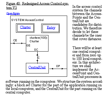
With the redesigned system, the application types are possibly modified in order to fit into the new structure. If this has been done, a division of the system into application and infrastructure parts has been obtained, and for the next systems (with the same infrastructure) it is a matter of exchanging the application types with either improved versions or new application types with e.g. new functionality.
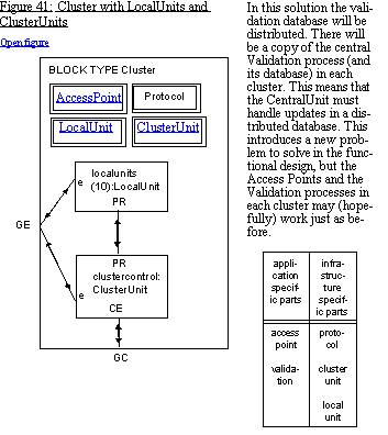
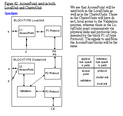
Having identified an infrastructure that seems to be common for many systems with almost the same application properties, TIMe advocates the re-designing of the system into a framework. TIMe gives guidelines on how frameworks can be defined in SDL. The following is a short introduction to how it is done.
As mentioned above, a usual definition of a framework is the following: "In object oriented systems, a set of classes that embodies an abstract design for solutions to a number of related problems."
TIMe puts a little more into frameworks than the definition above, and one reason is that SDL can specify the static structure of systems and not just a set of types.
A framework is a class/family of systems, with predefined structure so that a specific system only has to provide the specific "contents" of part of this structure. Frameworks often come about because an abstract (application specific) system description has to be supplemented by a large infrastructure part in order to be executable on a given platform. Instead of making the infrastructure part again for the next system with the same infrastructure on the same platform, a framework that embodies both the application and the infrastructure part is defined. In a framework the infrastructure is stable, while the application part may vary from system to system.
In the infrastructure design (see "Making infrastructure") the infrastructure part consists of the restructuring of the system into cluster units and local unit and the introduction of the protocol units. The application specific part is represented by the block type AccessPoint.
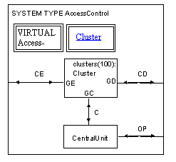
The system description of Figure 40 is turned into a framework simply by defining it as a system type and defining the application specific types as virtual types (in this case AccessPoint), see Figure 43.
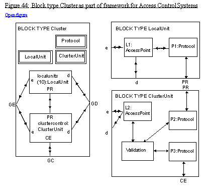
The Cluster block is almost as before: it uses the virtual block type AccessPoint (but it does not contain its definition), and it embodies the infrastructure parts needed for distribution (ClusterUnit, LocalUnit and Protocol), see Figure 44.
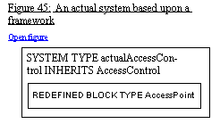
An actual system based upon a framework definition is described by defining a subtype of the framework system type, and redefining the virtual, application specific types, see Figure 45. The rules for redefinitions of virtual types in SDL ensures that the redefined AccessPoint will have the same interface as specified in the virtual definition (as a constraint) and thereby assumed by the rest of the system type.
Implementations are detailed and precise descriptions of the hardware and the software that a concrete system is made of. They define the physical construction of systems in a family. The software part will be expressed in programming languages such as Java, C++ or Pascal, while the hardware part will be expressed in a mixture of hardware description languages such as circuit diagrams, cabinet layout diagrams and VHDL. Software plays a dual role. Firstly, as a description to be read and understood outside the system, and secondly as an exact prescription of behaviour to be interpreted inside the system.
Concrete system
- The Application and the Framework software. State-of-the-art tools allow this software to be automatically derived.
- Special Application and Framework hardware. This will be special hardware designed to perform part of the Application or the Framework.
- The Platform, which consists of:
the support software which normally is a layered structure containing operating systems, middleware for distribution support, SDL runtime systems, DBMS and interface support;
the general hardware which normally is an network of computers.
What to do
For every new system development, the platform is an important design issue, as it determines important properties such as cost, reliability and flexibility. It also influences the way that Applications and Frameworks are implemented. The code which is generated for the Application and the Framework must be adapted somehow to the Platform. Here the Vendors of code generators use two different strategies. One is to adapt the code generator so the generated code fits the platform. Another is to adapt the generated code to fit different platforms by means of interface modules and/or macros.
Once the platform and the code generation strategy is defined, it is possible to rely on automatic code generation for Application and Framework evolution for those parts where SDL is used.
The main thing in this activity is to configure and to build system instances. Configuration can be applied both to the Application, the Framework, the Architecture, and the Implementation levels. Ideally we should perform configuration at the level where it belongs: functionality at the Application and/or Framework levels, and implementation at the Architecture and/or Implementation levels.
It is possible to perform some configuration at the Application and Framework levels using SDL, but due to limitations in the language, this is restricted.
The common practice in most companies today is therefore to do configuration on the implementation level using configuration files and tools like Make. (An alternative is to use special configuration languages.)
We recommend that a method for configuration and building of system instances is defined as part of the Architecture design work.

