Object and Property Models
- and the Languages for describing them

Systems in the scope of TIMe are characterised by consisting of concurrently executing objects that communicate by sending signals and whose behaviour is best described by states and transitions (reactive systems).
These systems tend to become large and complex - therefore it is not sufficient to describe the objects - the system also has to be structured in some way. Important properties are often described by use cases and by interactions between objects of the system.
UML [147], OMT [165] and many other methods use object diagrams and informal sketches in the specification and design of structure and a Statecharts-like notation for the specification of behaviour. TIMe uses one language for both: SDL.
SDL is a language recommended by ITU [102] for specifying structure and behaviour of systems that are reactive, concurrent, real-time, distributed and heterogeneous (not just telecommunication systems).
MSC is a notation recommended by ITU [110] for describing interaction scenarios.
TIMe recognizes that UML and SDL have slightly different approaches to object modeling, that these differences in some cases are beneficial (UML provides e.g. concepts for associations, while SDL does not) and that they in other cases may cause problems. Instead of a clear cut between object modeling in UML and SDL, TIMe defines its underlying approach to object orientation and provides guidelines on how to use both UML and SDL to support this.
This section will give an short introduction to the elements of this underlying approach to object orientation, and then introduce both UML and SDL, describing how they match this approach.
What is object modelling
The approach followed in this method is that an object model is regarded as a physical model, simulating the behaviour of either a real or imaginary part of the world. The main property of physical modeling is that it is based upon a conception and understanding of the application domain in terms of phenomena and concepts, and that physical models will have elements which directly reflect these phenomena and concepts. The physical model will consist of
Objects are characterised by variable attributes (data attributes), procedures (potential behaviour patterns) and behaviour. Objects in this approach may execute their behaviour concurrently with other objects. This kind of object is sometimes called " active objects" in contrast to " passive (data) objects".
Associated with objects and classes are a number of structure and abstraction mechanisms:
- Identification of objects and the classification of these into classes.
- Part/whole aggregation, that is objects as part of other objects.
- Relation composition, that is an object has relations to other objects instead of having them as parts.
- Specialization of classes. Classification relates all objects with the same set of properties into a class. Specialization is a mechanism for the structuring of sets of classes with similar properties into general and specialized classes.
- Localization of definitions: Some objects and classes are only meaningful within the context of a specific object or class.
class library
In addition, object oriented languages have support for some kind of library concept, enabling sets of related classes to be used in many different applications.
Domain and design object models
In order to bridge the gap between domain object modeling and design object modeling, TIMe provides guidelines for object modeling in
general, and
specialized guidelines for analysis and design.

TIMe uses UML for describing object models in case the formality of SDL is not required (or desired). The full TIMe book contains a tutorial on UML; the following is just an overview, covering the most important elements.
classes
UML object models consist of a set of classes. A class is defined by a class diagram with definition of attributes and operations.
attributes
In Figure 46 three classes are defined with attributes, and no operations.

Relations and communication connections
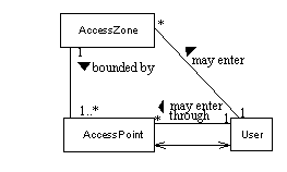
Classes may be related, as e.g. in the domain object model in Figure "The access control domain". AccessPoint and User are connected in order to specify that objects of these classes communicate.
specialization
Classes may inherit properties from a superclass, as in Figure 48, and thereby define more specialized classes.

Although UML supports multiple inheritance, TIMe advocates the use of single inheritance. One reason is that this is by far the best understood concept - another reason is that SDL only supports single inheritance.
part/whole -real aggregation
The fact that an object contains other objects is in UML specified by an aggregation association.
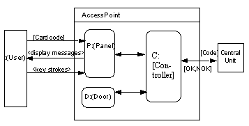
In order to really specify that the objects are part of the containing object and that relations to these part objects are only meaningful when contained in this object, TIMe uses the notation in Figure 49. It is specified that each AccessPoint consists of three objects (of classes Panel, Door and Controller) and that the environment communicates with some of these part objects. In UML the User in the environment would have associations to the class Panel in general, while what we want to express is that they only have associations with Panels as part of AccessPoints.
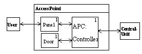
The corresponding can be expressed in UML using Composites, see Figure 50.
Localization
Classes defined locally to classes is not supported by UML. If this is important to express, then it may either be express informally or it may be specified in SDL.
system
An SDL system consist of a number of blocks, connected by channels. Possible communication by means of signals is indicated on the channels.
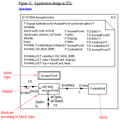
The system diagram in Figure 51 defines a system with one block CentralUnit and a set of 100 blocks of block type AccessPoint.
block
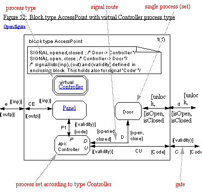
A block may either be further structured into blocks, or it may contain a number of processes. A block type defines a category of blocks with the same properties. The block type diagram in Figure 52 defines the AccessPoint referenced in the system diagram.
Each AccessPoint block will consist of three processes: Panel, Door and apc (access point controller) of process type Controller. The fact that the process type controller is defined to be virtual implies that it may be redefined in subtypes of AccessPoint.
The e and C on the outside of the frame are gates, that is connection points for channels - they are used in the system diagram above.
"class"
The block type in SDL corresponds to a class in UML. The instances of a block type are objects that contain other objects (blocks or processes).
communication connections
The processes of each AccessPoint block are connected by signal routes, and the signals on these indicate the possible communication between the processes. The signals used between the processes of a block can be defined locally to the block.
process: objects with behaviour
Processes execute concurrently, communicate by means of signal exchange (or remote procedure calls), and have the behaviour represented by an Extended Finite State Machine. The extensions are that processes may have variables and actions as part of transitions.
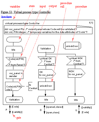
The process type Controller in Figure 52 is defined by the process type diagram in Figure 54. It defines the behaviour of Controller process by means of states and transitions.
attributes
The process type also defines the variable attributes of Controller processes: cur_panel of type PId (denoting a Panel process instance) and two integer attributes cid and PIN.
specialization
A type may be defined as a subtype of another type (the supertype), thereby inheriting all the properties defined for the supertype and possibly redefining the virtuals of the supertype.
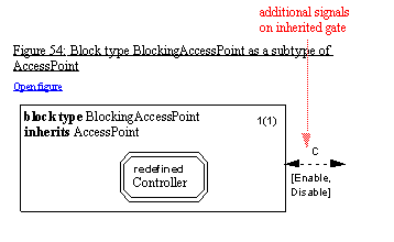
The subtype hierarchy which is specified in UML in Figure 48 will in the corresponding SDL design be represented by two block types inheriting the block type AccessPoint. In Figure 54 this is illustrated for BlockingAccessPoint.
The redefined process type Controller inherits the states and transitions of the virtual Controller from AccessPoint, and it adds states and transitions, as shown in Figure 55.
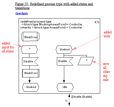
When the redefined Controller gets a Disable signal (in all states) it will enter the state Blocked, where it will only accept Enable, while all other signals will be saved (for consideration in other states).
package: the SDL library concept
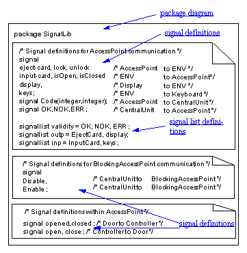
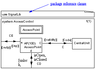
In addition to the structuring of systems into blocks of blocks or processes, SDL specifications can be organised in packages. A package is a collection of type definitions.
In Figure 56 the signal definitions for the access control domain have been collected in a package, and in Figure 57 they are used by a system diagram.
Guidelines for Domain Object Modeling
Domain Object Modeling is a special kind of Object Modeling. In addition to the general guidelines for Object Modeling found in TIMe, the following special guidelines apply:
-
Object classes with attributes, relations and connections
If attributes are not known, just introduce the class. Include any relation or communication link that may be important - in the design activity these will be refined and detailed (or thrown away). Do not use too much time on signals or communication links, unless they are stated in the Domain Statement.
Communication connections between classes indicate that there will be interaction property models between instances of these. For each of the communication connections check if this is important enough to call for interaction property models. -
Relations
Do not be afraid to use illustrative relations, but be aware that they may have to be "implemented" during design, while constructive relations may be implemented automatically through a data base part of the system. -
Attributes
If the type of an attribute is not known, simply introduce the attribute without any type, or introduce the attribute type as a class - this will then be defined during design. -
Aggregation
Use only real aggregation when it is obvious that this is the case. If in doubt, use relation aggregation, as this the most flexible. -
Behaviour associated with the object model
This will mostly be in terms of Interaction Models by use of MSC. If state information is important for the behaviour of an object, sketch an SDL process graph fragment for this part of the behaviour. -
Localisation (nesting)
Do not consider this unless it is quite obvious. In case SDL is used for domain object modeling, it will produce a set of packages of type definitions. These will mostly be independent of the actual context. If domain modeling goes so far as to define system and block types, then apply the general rules of localization.
Guidelines for Design Object Modeling
Object modeling for Design is a special kind of object modeling. The general guidelines of Object Modeling applies, with the following additions:
-
Object classes with attributes, relations and connections
Attributes will be defined by attribute types that are either reused or designed.
Associate signal lists with communication links.
Turn communication connections into signal routes or channels when designing in SDL. -
Relations
Stick to constructive relations if part of the product is to be implemented by a database component; otherwise "implement" all relations in SDL as data or signals. -
Attributes
Types of attributes must be defined, preferable as ADTs. -
Aggregation
Use real aggregation when it is obvious that this is the case, and use the SDL kind of aggregation. -
Behaviour associated with the object model
This may still be in terms of Interaction Models by use of MSC, but more SDL process graph fragments should be developed during Design.
SDL is more formal than UML. That is the reason why SDL is chosen for specification and design, and the reason for using UML for analysis and sketches.
SDL has more specialised concepts, so in a mapping from UML to SDL a number of decisions must be taken. Most UML classes of objects will map to process types, but in UML we may define attribute types as classes, while attributes in SDL are mapped to variables of data types. Aggregated objects in UML may either map to blocks (containing other blocks or processes) or to processes (containing services).
TIMe provides guidelines on this mapping - some of them are given below. Most of them are given in a short form just to give an impression of what kind of guidelines we have.
classes -> types
Classes in UML maps in general to types in SDL. Classes of objects with their own behaviour and with communication with other objects map to processes types, classes of container objects map to block types, and data object class map to SDL data types.
attributes -> variables
Attributes of objects map to variables of data types. A difference between UML and SDL is that attributes of UML objects are just of predefined types, while variables of SDL can be of user-defined types.
Operations
Operations are either mapped to remote procedures or to signals in combination with the corresponding transition and eventual reply signal.
Relations -> ?
Relations are not easily mapped to SDL. TIMe makes a distinction between constructive and illustrative relations. Being aware of this distinction when defining relations help in the mapping. Constructive relations will readily be implemented by a corresponding data base part of the system, while illustrative relation must be "implemented" in SDL.
Connections
Connections are mapped to signal routes/channels and corresponding gates on the types involved.
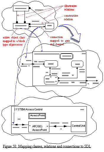
The relations in Figure 58 are for illustrative purposes in the mapping of the AccessPoint class to the AccessPoint block type, while the connection between AccessPoint and User maps to a gate e. The User class of objects is "mapped" in the first round to processes in the environment of the AccessPoint and in the second round to processes in the environment of the system.
In a further mapping of the classes in Figure 58, the classes be in addition be mapped to classes of objects in a database of which users may enter which access zones through which access point. In that mapping the relations are not just illustrative but may map to corresponding relations in the database.
Single Inheritance
It is recommended to use only single inheritance. This is readily mapped to the corresponding mechanism in SDL. The difference is that inheritance will have more implications in SDL than in UML, especially for inheritance between process types. While UML only specifies the inheritance of attributes and operations, inheritance for process types implies also the inheritance of behaviour also.
Single inheritance for data classes is mapped to corresponding inheritance for data types in SDL - the only problem being that only operators can be inherited.
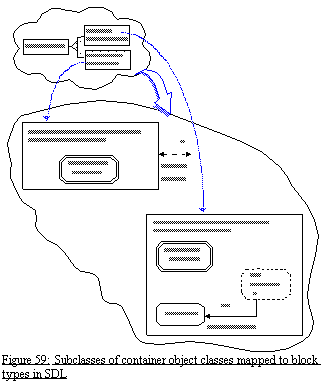
Inheritance between classes are not restricted to UML classes that map to process types or block types. Architecture of systems can be represented by a special system class in UML and if using the real aggregation of UML the content of the system objects can be readily expressed. Subclasses of such system object classes are mapped in the same way as in Figure 59, just substituting BLOCK with SYSTEM un the headings.
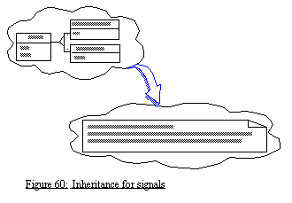
If the UML model contain inheritance between the types of events in use cases, then the mapping of this is to a corresponding inheritance between signal type definitions in SDL, see Figure 60.
Multiple inheritance
Multiple inheritance of the special kind where just one of the superclasses is a real superclass and the other are just "interface classes" (that is classes with only operations with no specification of behaviour, and no attributes) can in SDL be represented by inheritance combined with a gate for each interface superclass.
Multiple inheritance in general can be mapped into a type where the properties of the superclasses are copied into the type corresponding to the subclass (resolving the inheritance) or in some cases by aggregation. The first is not recommended, but must be done in some cases. The second alternative take different forms:
- If the superclasses are container classes, then the resulting block type may get a block for each superclass.
- If the superclasses are active classes corresponding to process types, then careful specification of these process types - so that they can work both as process types and as service types (that is no start transitions and input signals context parameters) - makes it possible to represent multiple inheritance by composing the process type by means of services. These services are then defined as subtypes of the services types corresponding to the superclasses, with one of them getting a start transition and actual signal parameters provided so that services do not have overlapping valid input signal sets.
- If the superclasses are data classes, then the resulting data type can be defined as a struct with each field being of the types corresponding to the superclasses.
Normally a problem with representing multiple inheritance by means of aggregation, in languages with object references, is that the objects of the resulting subclass cannot be referenced by object references typed with the superclasses. SDL does not have a general object reference concept and process instances can only be referenced by untyped PIds, so this is not a problem in SDL.
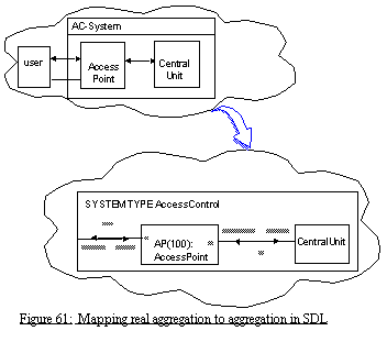
part/whole - real aggregation
In order to really specify that the objects are part of the containing object and that relations to these part objects are only meaningful in their property of being contained in this object, TIMe uses the notation in Figure 61. It is specified that a AC-System object consists of two objects (of class AccessPoints and CentralUnit), and that the environment communicates with some of these part objects. In UML the User in the environment would have associations to the class AccessPoint in general, while what we want to express is that they only have associations with AccessPoints as part of AC-System. The mapping to SDL is straight forward - here it is indicated that CentralUnit is not an object of a class but specified directly. The definition of the block type AccessPoint is left out in the mapping - it can be defined in a package or as part of the system.
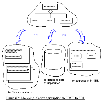
Relation aggregation
UML supports a special aggregate association. Depending on how this is used, it maps
What is property modelling
The properties characterize the objects identified in the Object Modelling. It is, however, not always the case that the object model has been created before the property model. During the identification of the objects, properties become clear, and during the description of properties, the objects and their relations must be established.
The following are some common properties of property descriptions:
- Property descriptions cover specific aspects;
-
Property descriptions may
overlap and
underlap;
As an example we are used to accepting that the MSC document will not comprise a description of all traces possible of the SDL model (object model). -
Property descriptions are often
declarative rather than imperative;
While the object model in SDL may be seen as a complete imperative description of the system, property models are often declarative meaning that they express something which either holds or does not hold in the model. - Property descriptions supplement object descriptions;
liveness properties: something good will eventually happen;
safety properties: something bad will never happen;
overview of functionality (functions and function lists, functional roles);
focus on interaction (use cases, MSC diagrams);
capacity and timing constraints;
physical constraints: temperature, humidity, power consumption, concrete interfaces,
other not so easily formalized properties: modifiability, security, error handling
The basic notation for property modelling is MSC-96. MSC highlights interaction between instances based on messages. MSC is most effective when the sequencing of messages between the acting objects is of major importance.
The full TIMe contains tutorials on MSC-92 and MSC-96 - the following is just an overview.
MSC concentrates on describing the message-sending between instances. The important invariant for messages is that a message must be sent before it is received.
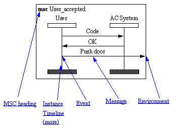
Figure 63 describes a very simple interaction between a user and an access control system. The user presents the personal code to the system which then returns that the user is eligible to enter the door. The user then pushes the door open.
instance
The actors of an MSC are called instances. They are described by an instance head and an instance end connected by a timeline as shown in Figure 64.
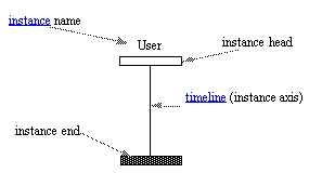
events
The instance head and instance end represent the start and end of events on the instance timeline within the MSC. The timeline of an instance contains a sequence of events.The most basic events are output and input of a message. Each message has exactly one output event and one input event. Messages are communicated between instances or between an instance and the environment. The environment is represented by the frame around the MSC diagram.
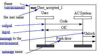
timeline
The events are ordered along each timeline, but events on different timelines are not ordered.
MSC describe communication between instances. An instance need not be a process in SDL terms. In Figure 65 we see that AC System is an SDL system.
MSC describes asynchronous communication. Input is normally interpreted as consumption of the message.
MSC document and Conditions
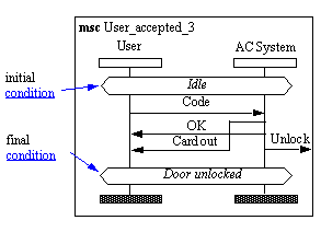
The set of mscs that are used to describe a specific piece of reality is called an MSC document. Relations between different mscs within a MSC document are called conditions. Combining two mscs where the end condition of the first is equal to the start condition of the second is legal. Combining mscs with unequal conditions is not legal. In Figure 66 there are two conditions, Idle and Door unlocked.
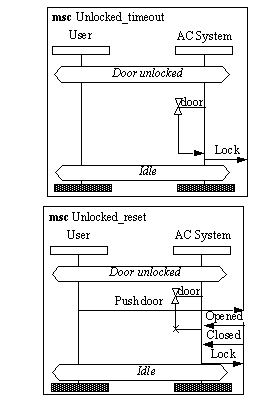
The two mscs Unlocked_reset and Unlocked_timeout in Figure 67 represent alternative courses of action from the state Door Unlocked.
Conditions are not synchronization primitives meaning that the different instances are not "within the condition" all at the same instant. The conditions are merely there for the combination of mscs.
Coregion
Coregion is a concept which is motivated by the fact that sometimes one does not care in which order a set of events occur.

In Figure 68 the User does not care whether he receives/consumes Card out or OK first.
Submsc
Submsc is motivated by the need to look into an instance for more communication details. Our AC System instance obviously contains a number of "smaller" instances. The requirement analysis may want to express details about the internal behavior of the system.
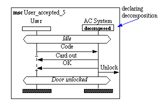
When we want to define a submsc of an instance we depict that in the instance header, see Figure 69. The decomposed instance must have the same interface as given by the instance in the MSC of higher granularity.
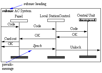
AC System of Figure 69 states that input of Code is followed in sequence by the outputs of Card out, Ok and Unlock. To ensure this in the submsc, we sometimes have to introduce additional (pseudo) messages, see Figure 70. This is an unfortunate aspect of this mechanism.
Guidelines for Domain Property Modeling
1. Identify separate services which should be offered in the domain.
2. For each service, provide a prose description.
3. For each service, define which roles provide the service.
4. For each service, make the description more precise by:
Formalizing (1): Transform those aspects which may into a formal language. The behavior should preferably be described in MSC or SDL.
Formalizing (2): Those aspects which do not lend themselves easily to descriptions in MSC or SDL should be described in semi-formal prose and structured comments.
Narrowing: Find out what questions were not addressed in the prose version and make decisions on these matters.
Supplement: Make sure that the precise description covers all those cases which the prose covers.
5. Associate every role with objects of the object model (Alignment).
Guidelines for Design Property Modeling
1. Take every service of the corresponding domain model and make sure that all roles are played by objects in the design structure. Remake all domain property descriptions such that they refer to the design software structure which is preferably in SDL.
2. Make the descriptions more detailed by:
Decomposition: Transform the descriptions such that they apply to the substructures of the objects and not only to the objects themselves.
Breaking down: Break down the messages and higher level protocols such that their internal structure becomes known.
Revelation: Reveal new instances and messages which prove to be interesting when a more detailed view is to be described.
3. Having reached a precise and detailed description, make sure that it is covered by the precise, but more abstract corresponding domain description.
4. Make sure to retain the structured comments and associated semi-formal prose of the domain descriptions in the corresponding design descriptions.
5. Use the design MSC property model as base for producing SDL process skeletons. The automatic production of skeletons can be used for discovering inconsistencies in the MSC property model. The produced skeletons should then be compared with the design object model and a complete design SDL model should be produced.
From MSC Property Models to SDL Object Models
The title of this section can be a little misleading - the fact is that what may be obtained is the construction of SDL Skeletons from MSC Property Models.
MSC is a formal language which is well suited to express cases of interaction between instances. SDL is a formal language which is well suited to express the total imperative behavior of processes one by one. The two notations have different perspectives on a system which supplement each other well.
We shall not always expect the MSC descriptions to cover all possible situations, but those situations which are covered are important. We should make sure that at least these situations are properly handled in the corresponding SDL descriptions.
TIMe provides a simple technique to produce SDL process skeletons for instances of MSCs. In order to have the produced SDL be a part of the final design it is necessary to make the MSCs so detailed that the instances of the MSCs correspond directly to processes of the SDL design. By careful use of local and global conditions in the MSCs, the SDL skeleton can be automatically derived.
From the SDL skeleton, the design process will add more behavior in order to cover all aspects of the process behavior. These supplements should not violate the behavior which was already generated in the skeleton. Since MSC does not have a formal data concept, the addition of tasks and decisions is one major activity when supplementing an SDL skeleton.
Even though a skeleton is only supplemented, it may be necessary to perform analysis to ensure that the final version of the SDL actually is consistent with the requirement MSCs.