Tutorial on UML
Introduction
Unified Modeling Language (UML) [22] is a language or notation intended for analysing, describing and documenting all aspects of a software intensive system. It is a further development from OMT [159] , Booch [20] , OOSE [109] and others methods and notations like David Harelís Statecharts [75] .
The structure of this tutorial is as follows:
- Overview of UML gives an overview of the main elements in UML.
- UML by example explains the use of UML through an example.
Overview of UML
UML can be used as a notation for Object Model in analysis and design when the formality of the SDL Object Model is not wanted. With UML you can represent different structures in a consistent and coherent way using object-oriented principles similar to those of SDL.
We use UML when SDL is not appropriate. Because it is less formal it can be used at an early stage to structure and analyse the concepts of an application domain before the functional design is made. In addition, it can be used to supplement SDL in the area of object modeling. SDL, for instance, does not support relations. The Object Models in UML can help you in your way from the description of the informal needs to a formal functional design in SDL.
This section will give a short introduction to the main elements and diagrams in UML.
UML have several different types of diagrams that can be used to describe a model from different point of views. These are:
-
Class diagrams
A Class diagram describes parts of the models static structure. -
Use Case diagrams
The Use Case diagram identifies the main system functions and shows the relationship between actors and the main system functions. -
Sequence diagrams
This diagram shows interaction as a set of messages exchanged between objects. -
Collaboration diagrams
A collaboration diagram show interaction organized around objects and their links to each other. -
Statechart diagrams
Statechart diagrams describes the behaviour to the instances of a class or the implementation of a classí operation. -
Activity diagrams
A activity diagram is a special form for state diagram where the states represent performance of operations and the transitions are triggered by the completion of the operations. -
Implementation diagrams
The implementation diagrams component diagram and deployment diagram, describe source code structure and run-time implementation structure.
Class diagram
Class diagrams describe the static structure to a part of a system. The diagram does not only show classes connected by static relationships (associations), but also packages, interfaces, objects and links etc. Specification of behaviour of a classí objects is not supported - this is regarded as part of property modeling and described in terms of functional roles by means MSCs. During design the behaviour of classes will correspond to behaviour of SDL processes and may then be defined by process graphs.
Classes
A class describes a set of objects with similar structure, behavior and relationships. Classes are defined by a set of attributes and operations in a class diagram. The class is shown as a rectangle with tree compartments. Both the attribute and operation compartments can be suppressed as shown in Figure 1 .

Attribute
An attribute describes a range of values that instances of the class may hold. It is defined by a name and a type. Additionally, an attribute can have properties like visibility (to other classes), multiplicity, an initial value and a property-string that indicates property values.
visibility name [multiplicity] : type-expression = initial-value {property-string}
Everything but the name may be suppressed. The type-expression can be either a class (that is a user defined type) or a predefined simple type like Integer or String.

Operation
Operations are specified by a name and a optional list of arguments.
visibility name ( parameterlist ) : return-type-expression {property-string}
When the return-type-expression is left out the operation does not return a value. The visibility and property-string can be suppressed.

Stereotype
A stereotype is a classification element and is used to indicate a difference in meaning or use between two elements with the same structure.
Objects
An object is an instance of a class. In UML an object is represented by a rectangle with one or more compartments (up to four compartments). The top compartment shows the name of the object and the name of the class. The other compartments can be suppressed.

An object represents a particular instance of a class and the same notation is used in collaboration diagrams to represent roles because roles have instance-like characteristics.
Object sets
Sets of objects can only be displayed through cardinalities of associations. Cardinality on association ends only tells how many instances that may be associated with a given number of source instances across the given association. It is not possible to specify how many instances a class may have. This can only be done in a note.
In UML many kinds of relationships can be modeled. The main types are shown in Figure 5 .

Association
An association defines a relationship between two or more classes. Binary associations are relationships between exactly two classes and a n-ary association is an association between three or more classes. The association may indicate that the classes communicate, but this is not necessarily true.
Since binary associations are easier to handle than n-ary associations it is generally recommended to avvoid using n-ary associations.
models the whole/part relationship, that is objects as parts of other objects. In UML there are two types of aggregation: aggregation and composition.
Aggregation
An aggregation (also called relation aggregation ) is a specialised association. It is specified by an aggregation association with a hollow diamond. A part in this type of aggregation can participate in several aggregates.
Composition
Composition (or " real aggregation ") is a stronger form of aggregation where the parts can not exist without the whole. The parts can only participate in one composite. Composition is shown as an association with a filled solid diamond nearest the class constituing the whole, or alternatively using the graphically nested form. The nested notation for composite aggregation is shown in Figure 6 .

The multiplicity mark is shown in the upper right corner of the symbol for the part. If it is omitted then the default multiplicity is many.
Objects outside the composite can have relations and connections to part objects, and these relations and connections are specific for these objects being part objects. The same relations and connections will not be valid for objects of these classes (here Panel, Door and Controller) used in other situations.
A nested element may have a rolename within the composition, the syntax being " rolename : classname", e.g. APC : Controller in Figure 6 .
Dependency
A dependency is a relationship that indicates that a model element is in some way dependent of another model element. All model elements must exist on the same level of abstraction or realisation.
Figure 7 shows an example that class A uses class B. The dependency association in the figure below is labelled with a «uses» stereotype. This dependency states that an object of class A requires the presence of an object of class B for its correct implementation or functioning.

Generalisation
A generalisation is a relationship between a more general element and a more specific element. Generalisation is a mechanism for structuring sets of classes with similar properties into general and specialised classes, as shown below in Figure 8 .

It is possible in UML for a specialised class (subclass) to have more than one superclass, while in SDL only one supertype is allowed. Therefore, to achieve a smoother transition between the UML-model and SDL-model, it is recommended not to use multiple inheritance.
Use case diagram
A use case diagram shows the relationships among actors and use cases. An actor is a role of an object or objects outside the system that interacts directly with it in a use case. The actor has class-like properties. A use case is an unit of functionality of the system or a class. One physical object may have different roles and therefore be modeled by several actors. There are three types of use case relationships:
-
Communicates
This relationship shows participation of an actor in a use case. This relationship is shown as a solid line between the actor and a use case, and is the only relationship between actors and use cases. -
Extends
An extends relationship from use case A to use case B indicates that an instance of use case B may include the behaviour of use case A. This is shown as a generalization arrow from the use case providing the extension to the base use case. The arrow is labeled with the stereotype «extends» . -
Uses
A uses relationship from use case A to use case B indicates that an instance of the use case A will also include the behaviour specified by use case B. This is shown as a generalization arrow from the use case doing the use to the use case being used. The arrow is labeled with the stereotype «uses» .
Use cases in UML are instantiated in collaborations or sequence diagrams.
Figure 9 shows a use case example from the access control system.

Sequence diagram
UML sequence diagram shows simple interactions between objects arranged in a time sequence. It shows the objects with their lifeline and the exchange of messages between objects. It may also show the creation of new objects.
The sequence diagram shows if the object is activated with a rectangular lifeline. When an object is not active, just existing, it has a dashed lifeline. An X at the end of the lifeline denotes that the object cease to exist, and can not be activated again.
The lifeline kan be split into two or more concurrent lifelines. Each lifeline corresponds to a conditional branch in the message flow. The separate lifeline can merge together at some later point in time.
Along the time axis timing marks can be specified. These timing marks can be used to give constraints, like specify the maximum time a message exchange may take.
Conditions for sending a message is given in braces in the sequence diagram.
[ condition ] message-name (parameter-list)
Figure 10 shows an example of an interaction between a user and parts of the access control system in UML. Figure 11 show the same interaction in a MSC diagram. In UML you have no timer concept, which means that you have to model a timer explicitly as an object.


Collaboration
A collaboration is a set of objects and relationships in a particular context. Collaboration diagrams are a static construct to show objects and messages involved in accomplishing a purpose or a set of purposes. Since time is not shown as a separate dimension in the collaboration diagram, the message sequences has to be determined by sequence numbers.
precondition / sequence-number * [ expression ] : returnvalue :=
message-name ( parameter-list )
Figure 12 below gives an example of a collaboration diagram. The figure shows sending of signals between some objects in the Access Control system when a user wants to enter an access zone.
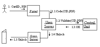
Collaboration diagrams can be used to illustrate signal/message exchange between objects in the system. In order to simplify the diagram and show all messages that may be passed between the objects, the sequence numbering may be skipped.
Statechart
A statechart diagram is a state machine that describes the behaviour to an object or the implementation of an operation. The diagram show:
- the states of an object (or interaction)
- an objectís response to stimuli (events) in terms of actions and responses
A statechart is attached to a class or a method. Statecharts can be used in the same way as SDL process graphs, to describe the behaviour of the objects of a class.
State
A state is a condition during the life of an object which:
An object waits in a state for a finite (non-instantaneous) amount of time.
A state can be decomposed into either concurrent substates or mutually exclusive disjoint substates but not both.
A state is shown as a rectangle with rounded corners. The state has one name compartment that may be empty. It may also have a compartment for internal actions. This compartment may be omitted. Figure 13 shows the four types of states in UML.

Action
Internal actions or activities are performed in response to events received while the object is in a state, without changing state. Actions are atomic and non-interruptible, and take an "insignificant" amount of time.
event-name (argument-list) [ guard ] / action-expression
Action expressions may use attributes and links of the owning object and parameters of incoming transitions.
The three following special actions represent reserved words that cannot be used for event names:
Event
An event is a "noteworthy occurrence" that might trigger a transition. An event has scope within the package it appears in, and may be used in any state diagrams for classes that have visibility inside the package. This means that an event is not local to a single class.
Transition
A transition means that an object would leave one state and enter a new state when an event occurs if specified conditions are satisfied. During the transition actions can be performed and messages may be sent.
Transitions can be complex, that is they may have multiple source states and target states.
A transition is shown as a solid arrow between two states. Actions during the transition is specified in a transition string with the following format:
event-name (argument-list) [ guard ] / action-list ^ send-clause
The send-clause has the following format:
destination-expression . message-name ( argument-list )
The destination-expression can identify several objects, and thus the message can be sent to a set of objects.
Implementation diagrams show aspects of implementation, including source code structure and run-time implementation structure. There are two types of implementation diagrams:
Component
A component diagram show the structure of the software components. A component is a reusable part that provides the physical packaging of model elements. The diagram show only component types and node types. Instances must be shown in a deployment diagram.
The component diagram consists of components connected by dashed-arrow dependency relationships or by physical containment representing composition relationship. Figure 14 shows a component diagram of the Access Control System.

Deployment diagram
Deployment diagrams show the configuration of run-time processing elements and the software components, processes and objects that lives on them. Components that donít exist as run-time entities are not shown in the deployment diagrams.
Node
A node is a run-time physical object that represents a processing resource. This includes computing devices as well as human resources or mechanical processing resources. Nodes may be represented as type and as instances. A node can contain component instances, which indicates that the components lives or runs on the node. Components in a deployment diagram may contain objects. Dashed-arrow dependencies connects components in the deployment diagram.
The deployment diagram shows nodes that are connected by communication associations. Migration between nodes or components can be shown with help of the dependency relationship and the stereotype «becomes». Figure 15 shows a deployment diagram.

Package
The main model structuring mechanism in UML is the package element. A package is a grouping of model elements, like classes, objects, associations, use cases, packages etc. Elements inside a package is owned by the package. The package define a name scope for the elements it contains and all the elements inside a package must have unique names. A package can be basis for storage, access and configuration control.
An example of a package is shown in Figure 16 . In the figure below the dashed arrow indicates that model elements in package AccessPoint uses or are related in some way to model elements in package CentralUnit.

In UML it is, as with OMT, difficult to explicitly show communication between entities in the system. One way to show communication between two classes is to use the navigability association between the communicating classes. The disadvantage is that you can not see the type of messages that can be passed between the classes.
To show all signals/messages that are communicated you can use collaboration diagrams without sequence numbering. This way you get a sketch over the signals in the system. The disadvantage with the collaboration diagram is that you can only see objects in the system not classes.
UML by example
This section explain the use of UML in TIMe by means of an example for both domain analysis object modeling and design object modeling applied to the Access Control System example. For a short introduction to the example, see First Introduction to the example .
Domain analysis object modeling
The main objective of domain object modeling is to improve understanding and communication by rigorously describing how concepts and phenomena in the domain are related. This is done by defining objects and classes that represent the domain phenomena and concepts. The object model also serves the purposes of
- giving more precise meaning to terms in the Domain Dictionary;
- providing references for property models;
- clarifying the basic needs existing in the domain.
In addition it should promote reuse by describing objects and classes that are common to most systems in the domain.
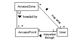
Based on a domain statement and a dictionary of terms, class/object diagrams which identifies the concepts and entities in the domain are made. One such domain diagram is illustrated in Figure 17 .
Use cases are used to identify the main system functions. Figure "Use case example of access control system" shows a possible use case for the Access Control System. The use cases are used as a basis to make interactions, that is sequence or collaboration diagrams. Figure "Sequence diagram showing access to an access zone" shows the use case described in Figure 9 as an interaction in a sequence diagram. Figure "A collaboration diagram showing user access" shows the use case in Figure 9 as an interaction in a collaboration diagram.
Contents of objects is only specified if it is a well-established fact in the domain; otherwise it is deferred to design object modeling. If contents of objects is to be specified, then composition can be used in order to specify a tighter part/whole relation than obtained with aggregation.
System analysis object modeling
System analysis involves the system as an object and considers its use environment. A system analysis produces a specification that covers those aspects of a system that are relevant for its external representation and use.
This is in TIMe done by so-called context specifications. Context specification can be made for any class of object, but for system analysis, the context of the system is the focus.
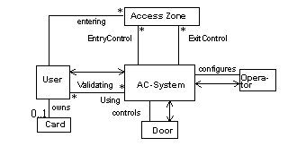
UML is used for this purpose by selecting the system as the primary class and then only consider classes of objects in the environment that the system has relations to or communicates with. Figure 18 is an example. The communication is shown with help of the navigability concept in UML.
Sometimes parts of the contents of the system object may be important, the parts may then be included in the system specification.
In design object modeling it is especially the aggregation (composition) support of UML that is used in order to specify the contents of both the system and its part objects.
Applied to the system as such, aggregation of UML gives the contents specification in Figure 19 . Note that relations and connections are still used, even though we now have individual objects or object sets as endpoints.
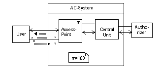
This design may be continued. Each access point is designed to contain three objects, one for handling the panel of the access point, one for handling the central unit and one for handling the door. This is specified by using composition, but now applied to the class AccessPoint, see Figure 20 .

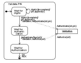
Figure 21 and Figure 22 show two statecharts for the AccessPointís Controller class. Figure 21 shows the behaviour of the Controller class at an general level. The state "Validate access code" is a composite state. When the state machine enters this state the state machine "Validate PIN" (shown in Figure 22 ) is activated.
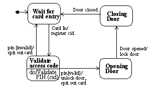
The state machine "Validate PIN" is shown in Figure 22 . Here it is shown explicitly that the signals/messages Authenticate and Authorize are sent to another object, namely the Validation object.
