Foundation of TIMe
Introduction
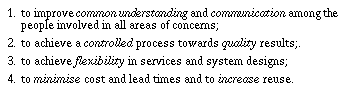
This theme is about the basic concepts, principles and ideas on which TIMe is founded. They are presented here to give an overview, and also an introduction to the underlying theories. Here we present the foundation for the "I" in TIMe (The Integrated Method).
The idea is that this theme will present the key features underpinning the methodology. It will start in textbook style, but will contain parts that are more of a reference nature. It will serve as the domain description for TIMe.
The criteria for being included here is that the topic is central to TIMe and to integration, and that it is used pervasively in the methodology.
This initial version contains only a brief overview as a starting point for discussions and agreement.
It expands somewhat on the central relationship between properties and objects. It is believed that the notion of roles will be central here. Relationships between objects and properties along with rules and operations on roles will be introduced.
Overview
The basic concepts and ideas are organised along the following dimensions:
- Areas of concern: how we organize descriptions in different areas of concern.
- Descriptions: how the descriptions in each area of concern are organised in formal models and other descriptions.
- Abstractions in models: the main abstractions we use in models to understand and describe systems for different purposes.
- System reference models: coarse architectures for each system abstraction (introduced to give methodological advice).
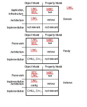
- Objects and properties: how models are organised into object models and property models and into specification and design. Also about how specifications are used before, during and after design synthesis.
- Activity categories the various categories of activities that operate on descriptions.
- Development steps and activities: the dynamic aspect of how the models and documents are developed and maintained. Flexible service evolution.
- Property models: how descriptions are related and relationships traced. Formal relationships, transformation and analysis, V&V.
- Descriptions and documents: how descriptions are put together and used in documents.
- Object models: how object models are composed/decomposed and related to each other by means of inheritance, instance-of, and other relationships. How properties relate to the object models.
- Requirements: how we make projections and describe properties on the various abstraction levels, and how we use properties to construct and analyse object models.
They will be described in the following chapters.
Areas of concern
Rationale
A major concern of most companies is to sell and deliver as many systems as possible. However, if their focus is entirely on the short term profits of each particular system delivery, they risk:
- that the overall quality is limited and gradually deteriorates;
- that the maintenance cost increases and eats up resources that could better be used elsewhere;
- that high cost of adaptation and production of each individual system severely reduces the profits.
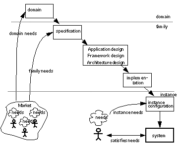
To alleviate these problems it is necessary to have a longer planning horizon and to shift focus from individual users and systems towards the more generic aspects of market segments and system families. For this purpose we distinguish between three areas of concern:
- Areas of concern
- Open figure
-
- Domains, which are the phenomena, concepts and processes that need to be supported (the problem) in a market segment irrespective of particular system solutions. By gaining better understanding of the needs existing in a problem domain we are in a better position to specify and design solutions that will provide real user value. We are also in a better position to identify general concepts that will be reusable across many systems.
-
System families,
which are generalised system or component types that can be adapted (configurated) and instantiated to fit into a suitable range of user environments. They represent the product base from which a company can make a business out of producing and selling instances. The idea is to focus development and maintenance effort mainly on the families in order to:
- reduce the cost and time needed to produce each particular instance;
- reduce the cost and time needed to maintain and evolve the product base.
- System instances, which are particular systems satisfying particular user environments. When a system family is defined, a system instance can be defined by reference to a system family using relatively simple configuration statements to binds the variability in the family. If there is no family however, it is necessary to define each system instance completely in self a contained instance description.This can only be recommended for one-of-a-kind developments.
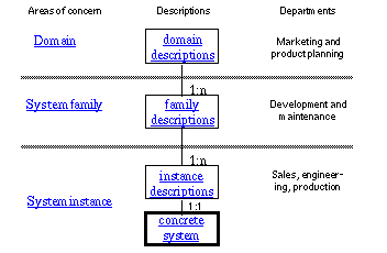
In each area of concern the method recommends to make the descriptions indicated in Figure 5-1, which will be elaborated in the next chapter.
Responsibilities
Responsibility for the different areas of concern will often rests with different departments within a company. Problem domain knowledge is essential for marketing and high level product planning. System families are the main products of the system- and development departments, while system instances are the main concern of the sales, engineering and production departments. In many companies these departments have difficulties communicating effectively with each other and this may lead to misunderstandings that are very expensive. They often have problems introducing new staff too because they lack a high level description of the problem domain and the systems they make. TIMe seeks to overcome these problems by providing high level domain and system models that can be shared across departments and thus provide a common ground of communication.
Advantages
TIMe offers the following advantages to the different departments:
-
Market and product planning:
- A clear picture of the needs and a sound foundation for product planning achieved through the domain descriptions.
- Precise communication with the development department (and the market) using common domain descriptions and family descriptions that make sense for both departments.
-
Development and maintenance:
- Better understanding of the user needs achieved through domain models.
- Support to all development steps.
- A constructive approach to family designs where reuse and validation is an integral part.
- Automatic generation of implementations.
- Service flexibility and architectural modularity.
- Reduced maintenance cost and improved control through maintenance at the family level.
-
Sales, engineering and production:
- Ease of instance configuration using system families with well defined variability.
- Clear feedback to development through precise specification of new features, and the possibility for development to assess the impact of new features on the design.
More
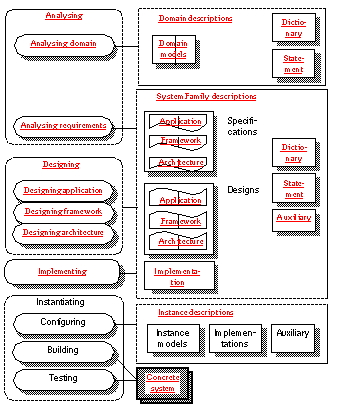
The various descriptions and the activities that produce them are elaborated in Activities and descriptions.
Descriptions
Rationale
The essence of systems engineering is to understand needs and to design systems having properties that satisfies the needs in a cost effective way. Without descriptions this is impossible. Descriptions are indispensable in systems engineering and all other engineering disciplines.
To a very large extent systems engineering is a matter of creating, understanding, analysing and transforming descriptions. Consequently, the selection of descriptions, their organisation and languages, are central to any systems engineering methodology.
Which descriptions?
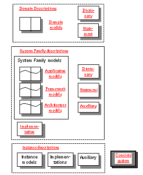
Within each area of concern the methodology recommends to make the models and descriptions indicated in Figure 5-2.
- The main descriptions used in TIMe
- Open figure
-
These descriptions are necessary and sufficient to achieve central goals of TIMe:
The descriptions have been carefully selected. They are neither too few, nor too many. There is little redundancy, as they describe different aspects and complement each other in a complete, concise and readable documentation. TIMe keeps the amount of temporary (throw away) descriptions to a minimum, and emphasizes descriptions that end up as final documentation. This does not prevent us from identifying partial descriptions that are useful in their own right, such as specifications, and to issue them in separate documents when needed.
We distinguish between formal models, implementations and other descriptions. The formal core of the methodology is the models which are expressed using the well defined languages UML, MSC and SDL.
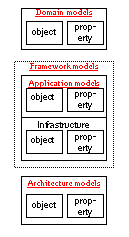
Domain
Domain descriptions are organised in:
- Domain models which are collections of classes with attributes, relations and associated properties. They may be organised in several abstractions. Since the domain is about general concepts and processes that are common to many systems, it is likely that some parts of the domain models will be used within the family models. These parts will often be quite stable, reusable and resilient to change.
- Domain statements which are concise statements about the domain, and is normally expressed in prose.
- Domain dictionaries over common domain terminology. It is important that the terminology used in other domain descriptions are harmonized with and defined in the dictionary.
- Domain auxiliary descriptions, which are any other description used. Will often be informal text and illustrations used to help reading the models.
Family
Family descriptions are organised in:
-
Family models which are object models and property models describing the family on several levels of abstraction:
- Applications that describe what the user environment want the system to do (user services).
- Frameworks that describe how applications are distributed and supported by an infrastructure. Frameworks and applications together define the complete system behaviour.
- Architectures that describe how frameworks and applications are realised in terms of hardware and software nodes.
- Family implementations which are implementations of family concepts. Here we find the general parts of implementations that are stable over all instances.
- Family statements which are concise statements about the family: its main purposes, its market and qualities.
- Family dictionaries which define the family specific terminology.
- Auxiliary descriptions which are any other description used, for instance test plans.
Instance
Instance Descriptions are organised in:
- Instance models which define the particular system instance on all abstraction levels. These may be self contained system models, but it is recommended to define instances as configurations of families.
- Implementations which are the instance specific implementations, such as configuration files.
- Auxiliary descriptions which are any other description of the instance, for instance a test suite.
Textual explanations
Textual explanations may be attached to models as well as to other descriptions.
Abstractions in models
Rationale
The concrete system that actually exists in the real world is composed from physical parts and software that executes to provide services to its users. In order to implement such systems we need detailed descriptions of their physical composition and their software. This is what we consider implementations.
However, in order to understand how the system is constructed and in particular to understand what it does for the users, implementations are not adequate. They are far too technical and detailed. Thus there is a conflict between the needs of the machine and the needs of the human. To satisfy the human, we need abstractions that remove the technical detail of implementations and allow us to concentrate fully on the aspects that are important for the human designer and user.
In order to bridge the conflicting needs of human interpretation on one hand and physical construction on the other, TIMe models the world using two main abstractions as illustrated in Figure 5-3:
- The main model abstractions
- Open figure
-
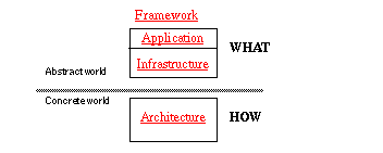
Abstract world models which emphasizes concepts and behaviour related to the user needs. They serve to define the behaviour in an abstract form that can be understood, communicated and analysed as much as possible without binding the implementation.
-
They will often be organised in a
Framework
with two main parts:
- an application that describes what the user environment want the system to do (user services);
- an infrastructure that describes additional behaviour and supporting functionality that needs consideration, e.g. in order to fully simulate its behaviour.
- Concrete world models describe the implementation architecture. This is a high level description of the physical implementation expressed in a unified notation. The purpose is to give a unified overview over the implementation and to document the major implementation design decisions.
The implementations are composed from a variety of notations and languages for hardware design and programming.
In principle all model abstractions may be used in all areas of concern. The focus in the domain is, however, mainly on the abstract world with emphasis on applications. This does not rule out the possibility of including infrastructures and even concrete world models in the domain where this is relevant.
Note that the main model abstractions is a rather coarse classification. There may more abstractions in a practical project.
Language dependency
To some extent the abstraction depends on the language used in descriptions too. But we have tried to follow some general underlying principles in TIMe that make the methodology less dependent on particular language than one could expect. To some extent it it possible to change language and still be able to use the principles of TIMe. For instance, during the development of TIMe there was a move from the SOON notation, through OMT to the UML notation.
Two purposes
All this is detail however. The main point is that we use abstractions primarily to improve human understanding and communication, and concrete systems to build the physical systems.
Model organisation
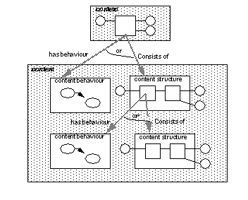
As explained in Objects and properties, models have facets illustrated in Figure 5-4. In general there are object models and property models. Seen together they define a context and a content. The context represents the entity being defined (e.g. a system type) as a "black" box and details of its environment, while the content details its internal composition in terms of object structures and behaviour.
- The facets of a type model
- Open figure
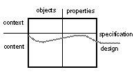
A specification covers those aspects of a model that are relevant for its external representation and use, while the design covers the internal composition and the internal properties.
The distinction between specifications and designs is not so important in domain models, while in system family models it is important. This has been illustrated for application, framework and architecture models in Figure 5-2.
Specifications
A specification covers those aspects of a model that are relevant for its external representation and use. The context part is often sufficient as a specification, but if parts of the content are important they may be included in the specification. Specifications are associated with the abstractions they being to.
Specifications are partial models
TIME emphasises the specifications are not special models, but integral parts of type models. The reason is that we want to minimise the amount of descriptions that are thrown away. Instead we want to make use of specifications throughout the lifetime of the model:
Specifications vs. designs
- first to express the required properties so they can be verified and validated;
- then to synthesise the design in a way that satisfies the specification;
- finally to describe its provided properties for later assessment, (re)use, validation and evolution purposes.
- Specification and design related
- Open figure
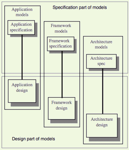
Specification and designs are often developed in different phases. Specification are produced early endplay a central role in quality and process control. Designs are produced later. Therefore in a development project they are developed by separate steps as illustrated in Figure 5-10.
Requirements specification
In TIMe we consider a requirements specification as a document. it is normally produced early in a development project and used as a contract for the design work. We force that specifications are used:
- for marketing;
- for retrieval;
- for validation of applications;
- for evolution.
Qualities of specifications
Important qualities of specifications are:
- precision and detail;
- unambiguity;
- traceability and verifiability;
- modularity that will support evolution and change.
System reference models
Rationale
Most people find that the most difficult part of systems engineering is to decide on architectural solutions for the systems. A well engineered architecture is clearly instrumental to the profitability of a product. Therefore it is essential that a methodology provide guidance and support to architectural solutions. Central competitive issues today are flexibility, time to market and cost. We seek modular designs:
- where changes can be confined in modules with standard interfaces;
- new services can be introduced quickly and safely;
- parts may be reused in many places.
To achieve this the methodology provide system reference models at the abstract and the concrete level. Another rationale is to identify parts that may have different requirements on development methods and often are developed by different teams.
Abstract system
In the abstract system we make a distinction between application and infrastructure, see Figure 5-6.
The application part provide the user services and is the most interesting part from a user point of view. Changing or adding services to the system means to modify the application part.
- It consists of the following main sub-parts:
- Interface given objects that encapsulate the interface specific behaviour, e.g. the behaviour of graphic user interfaces and protocol stacks. By isolating this part from the rest it is possible to change the interfaces without affecting the other parts.
- System given objects that encapsulate the system specific services and information. These are particular for this system family and not common to all systems in a problem domain.
- Domain given objects that encapsulate services and information that are common to the entire problem domain. These objects are reused across system families.
The infrastructure part contains additional behaviour needed to fully understand and analyse what the system does (the complete system behaviour). Here we find object that support distribution, system administration and other facilities not directly related to user services.
- Reference models for abstract and concrete system
- Open figure
-
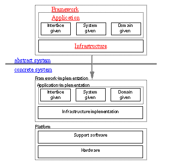
Whenever practical the application and the infrastructure will be put together in an application framework that serves to simplify the definition of new abstract systems.
Concrete system
A Concrete system consists of:
- The implementation of the abstract system in software and hardware. Parts of this software may be automatically derived using state-of-the-art tools. Software plays a dual role. Firstly, as a description to be read and understood outside the system, and secondly as an exact prescription of behaviour to be interpreted inside the system.
- The support software which normally is a layered structure containing operating systems, middelware for distribution support, SDL runtime systems, DBMS and interface support.
- The hardware.
The role of the implementation architecture model is to define the overall architecture of the concrete system and define how the abstract systems are mapped to (abstract system) implementations.
Independent parts
Note that the various parts of the system models are quite independent and may be modified with little impact on each other. It is, for instance, possible to change the implementation platform without needing to modify the application. Thus an application may survive several platform generations and thereby provide better return of investment. Similarly a platform may support several applications. Adding or changing services is mainly performed in the application, leaving other parts unchanged.
We will distinguish between a system and its descriptions. A system is part of the real world and is able to perform behaviour, thus serving its users. Descriptions, on the other hand, represent the system and enable us to understand, analyse and communicate about it. Descriptions are also part of the real world, but they are distinct from the system and cannot perform behaviour and serve users like the system does. What they can do is to define the rules of behaviour.
Designers tend not to distinguish clearly between descriptions and systems. For them the word "system" often means "system description". For the users, however, the difference is profound. From the designers point of view, evolution is mainly a matter of change and adaptation of descriptions. From the market, or user, point of view, it is a matter of change and adaptation of systems. Maintaining the relationship between systems and descriptions is therefore essential for successful evolution.
It should be noted that any particular concrete system may be composed from more than one application. TIMe supports the development of heterogeneous distributed systems using a mixture of languages and methods.
Descriptions may be structured in many ways. Some will be easy to comprehend and relate to the real system, while others may be hard. A compact description is no better than a larger one, if it is harder to relate to reality.
Readability through structural similarity
- In order to maximize our ability to understand and predict what will happen in reality, we will emphasize that design descriptions are structured in a way that closely reflects the system. This is particularly important for the behaviour part. We will seek to achieve behaviour descriptions that are structurally similar to actual behaviour (i.e. state oriented behaviour descriptions).
Our quest for structural similarity have caused us to adopt object- and state orientation as the primary perspectives for system description.
Objects and properties
Object and property models
As can be seen from Figure 5-7, we use two related model types:
- Object and property models
- Open figure
-
- Object models. These are models that describe how a system or component is composed from objects, connections and relationships. They are constructive in the sense that they describe how an entity is composed from parts, be it abstract or concrete. This is the perspective of designers.
- Property models. These are models that state properties of a system or component without prescribing a particular construction. They are not constructive, but used to characterise an entity from the outside. There are many kinds of properties: behaviour properties, performance properties, maintenance properties, etc. This is the perspective preferred by users and sales persons. It is also the main perspective in specifications.
A central idea in TIMe is that every object (and system) is characterised by properties that can be used:
- to understand what the object does;
- to check that it is suitable for the environment where it is used;
- to synthesize the content design;
- to verify that the content design satisfy the properties;
- to retrieve the object from a library (given some required properties).
Property models are not necessarily bound to object models, but object models shall normally be bound to property models.This holds for all object models: domain models, application models, architecture models.
Purposes
The purposes of separating Property Models from object models are:
- to facilitate reuse of property descriptions;
- to ensure consistency by describing properties shared among objects in one place;
- to support reuse of objects by using required properties to search for objects that provide the same (or equivalent) properties;
- to support V&V by matching provided and required properties;
- to facilitate property oriented product planning, marketing and system configuration.
There are many kinds of properties: behaviour properties, performance properties, maintenance properties, etc. In TIMe, the property models will contain properties that are relevant for the corresponding object models:
- Abstract properties are associated with the abstract object models. Since abstract models focus on functionality (behaviour) these properties are often termed Functional properties. They characterise the behaviour of objects, and the collaboration between objects. They are mostly expressed in the style of Use Cases using the MSC notation.
- Concrete world properties are associated with the concrete models and state properties relevant for the implementation. They are often termed Non-functional properties and characterizes the implementation.
Context and content
Object models consists of two main parts, illustrated in Figure 5-8:
- The facets of a type model
- Open figure
-
- The context, where the object being defined is considered as a black box and the environment is detailed. This serve to describe the environment and the interfaces as well as other external relationships. By associating property models with the context it is possible to specify the external properties the object provides as well as the properties it require from its environment.
- The content, where the internal composition is defined in terms of component objects and behaviour. This may involve a tree structured decomposition over several aggregation levels. Property models associated with the content will specify properties of internal objects and interfaces. Obviously the content properties shall satisfy the context properties (in some sense).
The object-property dimension and the context-content dimension give every type model four facets as indicated in Figure 5-8.
Specifications
A specification covers those aspects of a model that are relevant for its external representation and use. The context part is often sufficient as a specification, but if parts of the content is important it may be included in the specification. Specifications are associated with the abstractions they belong to:
- Application specifications are concerned with functional requirements directly relating to user needs, i.e. user services and interfaces.
- Framework specifications are concerned with the infrastructure functionality, e.g. internal protocols, distribution support and system administration.
- Architecture specifications focus on (non-functional) requirements to the implementation, e.g. the choice of technology, the implementation principles, platform requirements, performance requirements.
A design cycle start by making a specification where the context object model and the context property models are defined. It then makes a design where the content object model and the content property models are defined. In the specification, the emphasis is on properties, while in design it is on objects. But the properties of the specification shall be satisfied by the design.
Specifications serve three main purposes:
- before the content is designed, they serve to express the required properties, also called requirements;
- during design they are used constructively to synthesize the content using a mixture of transformation and composition with reuse;
- after the content is designed they serve to express the provided properties.
The specification serve as a datasheet for a designer looking for existing components to (re)use in a design. They also serve to describe interfaces in a way that simplify validation of interconnections.
Activity categories
Viewed from the development processes, activities can be classified in these categories:
- Make activities. Activities that make or synthesise descriptions ( models) for the first time, possibly based on other descriptions, e.g. to make SDL process graphs from requirements expressed using MSC. A variety of techniques are used: transformation, translation, composition, decomposition and reuse.
- Evolve activities. Activities which perform (incremental) development of existing descriptions. They may either add new properties, e.g. add a new service to existing Application models, or change existing properties, e.g. correct errors.
- Harmonise activities. Activities which ensure that models/descriptions are consistent with each other, e.g. to make the domain dictionary consistent with the domain object models. The activity will ensure that certain relationships that should hold between models/descriptions are satisfied. For instance that an object model satisfies the properties specified in a property model, or that a content satisfies a context.
- Analyse activities. Activities that analyse a model/description, e.g to verify that a design satisfies given properties.
Make activities
The make activities can be subdivided according to the the main facets of a model (see Objects and properties) into:
- Make specification: creates the specification part for the first time. It will also be concerned with identifying external types (e.g. SDL packages) used as components.
- Make structure design: synthesises the design object structure with associated properties for the first time. As part of this it identifies the component types used in the structure. For those that must be developed from scratch the same basic make activities are applied again. This activity follow guidelines that seeks to ensure consistency with the specification.
- Make behaviour design: synthesises the behaviour of object types (e.g. the process graph of an SDL process). This activity too, follows guidelines that seek to ensure consistency with the specification.
It is here assumed that the content of a model is either a structure or a behaviour.
Evolve activities
After a description is made the first time, it may be evolved by adding, modifying or removing features. This is performed by evolve activities. They are different from make activities because the target description already exists when they are invoked. They must consider the impact on the existing target and carry out modifications according to the new requirements. They must also consider whether the result should be treated as a revision to replace the previous target, or as a variant that shall co-exist with it.
TIMe emphasises flexibility in the design solutions in order to support an evolutionary approach and service flexibility.
Harmonise activities
Harmonisation is the general term we will use for maintaining desired relationships between descriptions. Harmonisation applies both to the descriptions within an area of concern such as between the the domain descriptions, and between different areas of concern such as the between domain object model and the application object model. Within the domain, for instance, we harmonise the terminology in the dictionary, the statement and the models. It also applies to the different abstractions: we want the application models and the implementations to be consistent.
Ideally, harmonisation should take place after each step in order to keep the descriptions consistent at all times. In practice, however, we must accept some deviation from this ideal. A central point in TIMe is that object descriptions and property descriptions represent two different perspectives on some entity (usually a type). This implies that, that even if domain-, design- and implementation descriptions are not maintained so that they are consistent, then the object and property descriptions within the same models (e.g. the domain models) are consistent. It also implies that the activities producing these will have a tighter interaction than the activities from different areas.
Constructive design methods that will ensure consistency between the required and provided properties will be emphasised. Still it will not be feasible to ensure that they are consistent at all times.
An important aspect to harmonisation is traceability. As a minimum it shall be possible to trace how each requirement is mapped to design.
Analyse activities
These are activities that derive properties from descriptions and compare descriptions. They are typically used to verify and to validate descriptions on the different abstraction levels. For instance to see if an object type is able to provide some required properties, or to check that an application system is deadlock-free.
In general, analysis seeks to check that desired relationships hold between models/descriptions.
Analysis and harmonisation is closely related to the various relationships that may be defined between descriptions.
Languages and notations
The main modelling languages are summarised in Figure 5-9.
- The languages used in TIMe models
- Open figure
-
Domain
Domain models will normally have most emphasis on the abstract world which will be modelled using UML and MSC . SDL may be used in cases where the state transition behaviour is important.
However there may be cases where concrete world models are appropriate, e.g. to describe physical conditions, implementation principles or non-functional properties that apply throughout the domain.
Family
Both abstract and concrete world models are relevant for families. Frameworks (applications and infrastructures) are primarily expressed in SDL, but UML is used as a supplement both for high level specifications and for parts where SDL is less suited, e.g. database applications. For reactive systems, SDL-92 will be used as the main language. However, SDL is best suited for the control part of reactive behaviour, and less well suited for pure transformations (algorithms), data-oriented applications and user interfaces. As modern systems often need to integrate these other aspects, TIMe provides support for these parts as well based on the Unified Modelling Language, UML.
Instance
In the instance area of concern, the main thing is to configure and to build a system instance. This can be done both on the abstract level, using SDL, in the Implementation Architecture, and in the implementation. The common practice in most companies is to do this on the implementation level using configuration files and tools like Make. An alternative is to use special configuration languages in this area.
Mixed modelling
TIMe will allow systems to be described by a mixture of notations and languages in order to cover all system aspects. It will for instance be possible to model control behaviour using SDL and data manipulation using UML.
This means that a concrete system well may be composed from parts that are modelled and developed using different techniques. Each of these parts may then be considered a system in its own right from a modelling point of view. Consequently, what we choose to consider a system will depend on the circumstances, and need not always be the complete system that will be delivered to customers.
What we choose to model as an SDL system may be just the parts where SDL is well suited. Other parts may be modelled in UML. The practical implications are that the SDL system concept will be less important. In stead the focus should be on generic component types that may be put together and configured as easily as possible into complete systems. In SDL terms this means to focus more on block types and process types than on systems.
Another implication is that some way to define complete systems composed from inhomogeneous parts is needed. For this purpose UML will be used for high level architectures.
Development steps and activities
Assuming that the models are the key to systems engineering, how are we going to use them during the systems engineering processes?
Minimum throw away
Bear in mind that we make descriptions for two main purposes:
- to foster learning and communication during the systems engineering processes;
- to document the results at the end.
It is not obvious that these two purposes can be served by the same set of descriptions. Indeed, there are methodologies that emphasizes the first purpose and produces many descriptions that only serve the process and not the final product. The models we use in TIMe have been selected to serve both these purposes. TIMe seeks to keep the amount of temporary (throw away) descriptions to a minimum, and emphasizes descriptions that end up as final documentation. This does not prevent us from identifying partial descriptions that are useful in their own right, such as specifications, and to issue them in separate documents when needed.
In systems engineering projects, the various models and descriptions are developed gradually in an order that help to illuminate critical issues and make decisions at the right points during a systems engineering process. They end up to complement each other in a complete and readable documentation.
Steps
The descriptions within different areas of concern and on different abstraction levels are developed in steps that help to reduce risk, and to improve quality and control. This help to give better control and also to use the skills of different people better and to run activities in parallel.
Each object type model is developed in two main steps: first the specification step where the specification part (interfaces and the required properties) is made, and then the synthesis step where the design part is developed.The main development cycles are illustrated in Figure 5-10.
- The main cycles
- Open figure
This is of course a simplified illustration of the main steps. Considered over time we will se that the descriptions evolve gradually, that there are many iterations and that changes take place due to better insight, new requirements and new technology. We will also see that there are other, smaller cycles. For instance: to add a new service or feature to an existing product we need not modify the domain. To produce a customized instance we only need to add a new instance configuration.
Many strategies
One should not jump to the conclusion that TIMe only supports the classical "waterfall" model! It is up to the actual projects to determine whether they will adopt a waterfall strategy, a prototyping strategy, use incremental development or whatever.
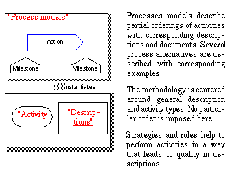
What TIMe provides is a general description of the central activities including strategies and rules, see Figure 5-11. The activities are described in Activity overview.
- The main activities in TIMe
- Open figure
-
It is then up to each project to plan and carry out a process where they are performed in a suitable order. Some typical process cases are presented in Process models. Processes will invoke the activities and evolve the descriptions through a sequence om milestones and intermediate steps as illustrated in Figure 5-12.
- The methodology context
- Open figure
-
Activities and processes are about HOW TO DO IT. Or more precisely: how to carry out property oriented development projects. They provides the practical guide-lines needed to achieve a controlled process starting with the initial needs and ideas and ending with quality products ready to be installed at customer sites.
To read more
For the activities needed to develop the results, see Activity overview. For general development processes, see Process Models. For process examples, see Example.
Links and relationships
Rationale
It is clearly necessary to establish and maintain clear and traceable relationships between the various descriptions and models. There are several reasons:
- Since each model or description is concerned with a limited area of concern and abstraction, a complete documentation is made up of a set of interrelated models/descriptions. In order to read and understand this complete documentation it must be possible for a reader to navigate in the descriptions and to understand the relationships as easily as possible.
-
We need to trace the relationships from required properties to the design objects where they are provided. There are at least, two reasons for this:
- quality assurance need to check that every requirement is satisfied;
- when a requirement is changed we need to analyse what impact it will have on the design.
- We need to ensure consistency both between models and within models. This can be achieved either correctively by comparing models or constructively by ensuring that models are derived according to rules, e.g. by automatically translating from abstract models to implementations.
Relationships
Relationships between all the models and other descriptions shown in Figure 5-2 must be defined. There are:
-
Domain to family relations:
- object to object;
- property to property.
-
Family to instance relations:
- object to object;
- property to property.
-
Family internal relations:
- application to framework relations,
- implementation relations,
- property to object relations,
- specification to design relations,
- validity of interfaces,
- dictionary, statement and model relationships.
- Domain internal relations:
- dictionary, statement and model relationships.
- Instance internal relations
The precise definition of relationships depend on the languages that are used. They will be elaborated under the various description modules.
Descriptions and documents
In the systems engineering literature and practice, the terms "documents", "descriptions" and "models" appear frequently. Do they mean the same, or is there a difference in meaning? We will use the terms to mean two different, but related, things:
- Models and descriptions express some meaning within an area of concern. They may use a formal language, like SDL, or informal text and drawings. The form does not matter. The point is that models and descriptions are intended to mean something and to be up to date on that.
- Documents are carriers of models, descriptions and other information. Documents are often made for specific occasions and audiences, e.g. a contract, a review document, a user manual. A document can contain only parts of a model or it may contain several. Likewise may a model or description be contained in several documents.
- Model - Document relationship
- Open figure
-
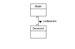
Why this distinction? Because it enable us to distinguish between the information which is essentially needed to develop and understand quality systems (the models and other descriptions) and the accidental form used to present it on various occasions (the documents). The n:m relationship, between models and document indicates that documents and models should be maintained separately.
Normally, many documents are produced during a project. As a minimum, formal communications and decision points in a project will be based on documents. The structure and contents chosen for each particular document will depend on the occasion and the audience that particular document is intended for. Most models, on the other hand, are not intended for any particular occasion or audience. They express up to date information about some area of concern. A domain model, for instance, has meaning in terms of a domain and is stable as long as the domain remains the same.
Some companies are very document oriented. The work proceed through a sequence of documents and much of the effort is centered on document production. To a large extent models and descriptions exist only as part of documents. Consequently, where to find complete and up to date models and descriptions are not always obvious. This problem may be amplified if different departments prefer to express essentially the same information in different ways. As a result, much effort is spent on translating and repeating information.
- A document oriented organisation
- Open figure
-
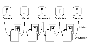
The cost associated with this repetition is probably the least problem. More serious is the likelihood that the models seen by different people are inconsistent. Even more serious is the tendency to be preoccupied with document form rather than model content. Another common problem is that textual specifications are structured according to document standards and not according to the model of the system.
The other extreme is a purely model and description oriented organisation, where everything is centered around models and descriptions. In practice there will be a mixture. The question is how much emphasis there is on such models compared to documents. Are models the main results on which communication, quality control and progress measurements are based, or is it documents? Is one consistent and complete set of interrelated models sought, or is the collection of more or less complete models found around in various documents considered good enough?
- A model oriented organisation
- Open figure
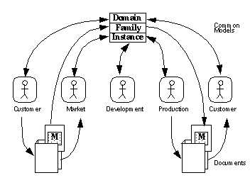
TIMe recommends to be mainly model and description oriented, but recognizes that documents are needed addition for external communication, formal reviews and contracts, see Figure 5-15. The basis for communication and common understanding, is the models. It is therefore essential that all team members see the same models. Since models are gradually developed and updated in the course of a project it is also essential that the team members see the same versions.
Object models
The characteristics of objects
Objects have the following characteristics:
- Physical substance: we know that e.g. a subscriber is a physical object with independent, sequential behaviour. There is no point in denying this fact by modelling a subscriber as several objects. Likewise, physical channels will terminate on objects and not functions.
- Concurrency: objects operate concurrently (independently). The mode of concurrency may either be true parallelism or some form of quasi-parallelism, e.g. alternating.
- Closed behaviour: objects are complete units of sequential behaviour in the sense that their action sequences are closed and fully defined.
- Signal interface: interaction with other objects take place by signal interchange, not by direct data manipulation or action chaining.
- Data encapsulation: every data item belongs to some object, data should be distributed according to the need-to-know principle
Good objects have the following additional qualities:
- Achievement of information hiding, interaction hiding or operation hiding. Do not use objects where no hiding is achieved! (the object should provide some function to its environment, helping to simplify the environment)
- Clear and concise behaviour description in state oriented form.
- Application independence, making the object type reusable.
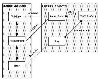
Active and passive objects
Classification
We generally classify objects appearing in object models in two categories depending on their purpose in the model:
- Passive objects. The purpose of passive objects is to represent something we need to know about. Descriptions of passive objects will abstract from physical details of the entities they represent and model only what we need to know about them. The behaviour of passive objects will normally be very different from the actual behaviour of the objects they represent. A passive object representing a person has a simple behaviour concerned with updating of attributes and relationships (data), while the real person itself has an extremely complex behaviour.
- Active objects. The purpose of active objects is to take care of transformations and control we need to perform. They are justified more by what they do than by what they represent. Their behaviour is often detailed and related to physical processes. A call handling process in a telephone system, is one example. It interacts with physical users and controls physical connections.
Note that this classification is according to how we want to describe objects, and not necessarily depending on real object properties. The same physical object may well be described both as a passive and an active object. An access point in the Access Control system, for instance, is a passive object in the validation database, and at the same time an active object controlling user access to the system. In a way the passive objects are like property descriptions of the active.
Relationship
Passive and active objects are related as illustrated in Figure 5-16. We will normally describe active and passive objects in separate but related descriptions.
- Passive objects may describe active objects and be contained in active objects
- Open figure
The relationship between passive objects and the objects they describe, i.e. the meaning, is quite important and central to the correctness of a system. TIMe will seek to take care of this relationship and use it constructively during synthesis and correctively in V&V.
Object Modelling has traditionally been used only for passive objects to be handled by information systems. TIMe will also cover active objects performing general functions.
Traditional data models are object models describing passive objects.
Anatomy of object models
Object models are made where we need a constructive description at a given level of abstraction.
- General organisation of object models
- Open figure
Object models can be organised in many ways. TIMe assumes that object models are organised as illustrated in Figure 5-17 to have two main parts:
- Context. The context describes the object type as a black box in an environment. Interfaces, associations and object roles in the environment are detailed. Property models associated with the context will specify the external properties (to be) provided from the object and properties that the object require from actors in the environment.
-
Content.
In the case the type is an aggregate of objects, the content is a
structure
of component objects. Each component may be further decomposed in the same way as the type being defined. There is no limits on the number of decomposition levels.
In the case the type is a single object, the content is a behaviour definition stating the state transition behaviour of the object type.
In the family area the emphasis will be on object type models. A type may be defined in two ways:
- By explicit and local definition of the content. This is what is illustrated in Figure 5-17.
- By inheritance from a super-type, possibly adding and/or redefining some components.
For each component, two similar options apply: it may either be defined, as illustrated in Figure 5-17, by explicit local definition, or by instantiating an object type defined elsewhere.
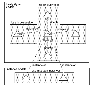
If we represent and entire object model, like the one in Figure 5-17, by a triangle, we may illustrate these various ways that type models may be used as in Figure 5-18. It illustrates that a type may be used in three "dimensions": in sub-types, in components and in system instances.
- Relationships between object models
- Open figure
For each type model, property models will be associated with the context and the content, see Property models.
Depending on the abstraction and the problem, we will use either UML or SDL for object modelling. These languages are based on object oriented principles supporting types, inheritance and instantiation and can be used to make object models according to the principles explained above.
To read more
The principles for object modelling are further explained in Object modelling.
Property models
Functional properties and roles
What
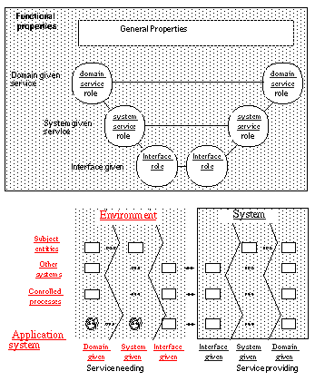
Functional properties characterise the behaviour of abstract systems. In TIMe, abstract systems are modelled in Application models and Framework models. Figure 5-19 illustrates how functional properties are related to Application systems.
Categories of functional properties
Functional properties are classified in the following categories:
- General properties, which are properties that can be expressed independently of particular objects, services or interfaces.
- Service properties, which are properties related to specific services. Important aspects are the Service roles that objects shall play to perform the service and the interaction behaviour between these roles. These service roles are played by the domain given and the system given objects, as indicated in Figure 5-19
- Interfaces properties, which are properties related to specific interfaces. Important aspects are the Interface roles that objects on both sides of the interface shall play and the collaboration between those. Interface roles are played by interface given objects.
- Data properties. These express what can be said about the data a system contains in terms of what they mean for the environment.
Figure 5-19 illustrates how the properties relate to the different parts of an application system. Note that interface and service properties involve at least two objects where some are in the environment and some in the content. Also note that properties may be related by layering.
- Functional properties related to application systems
- Open figure
-
General properties
An important class of general properties is safety properties, which state what should never happen, typically:
- deadlocks;
- unspecified receptions;
- livelocks.
Service properties
It is well known that users tend to think in terms of services and interfaces. Therefore it is customary to characterise systems using a service oriented perspective. This is best explained in contrast to the object oriented perspective as illustrated in Figure 5-20. Many services will naturally involve several objects. A normal call in a telephone system involves at least two objects: the initiating subscriber and the terminating subscriber. There is no point in one without the other. The service perspective allows us to see the two in combination, but only to see fragments of each object. In the object perspective we are able to see the complete object, but only fragments of each service.
Interfaces properties
Services are controlled via interfaces, and interfaces may have properties of their own. These properties (protocols) must be followed by both sides of the interface, as illustrated in Figure 5-20. Objects may have several interfaces, and the same interface may apply to several objects. Indeed, standard interfaces is a key to achieve architectural flexibility. There may well be mutual dependencies between interfaces. The behaviour a user experiences on a given panel depends on the access rights the user has been granted through the operator terminal. Such dependencies will be visible as non-deterministic choices at the observed interface, but the exact nature of the influence will be hidden.
Data properties
The data stored in a system or object is central to its purpose. In a specification the interesting thing is what the system (or object) knows about the environment. In other words: what are the associations between (passive objects in) the system and the environment.
About roles
Why roles?
We can now make two important observations:
- Service and interface properties will span several objects. They are composed from (sub)properties of different objects. An important advantage of the property perspective is the possibility to combine and describe properties of different objects that belong together in one place. This will be utilized to describe service and interface properties in one place such that they may be used to characterise all object types using the interface.
- Object properties are composed from sub-properties belonging to different services and interfaces. However, composition of properties into objects is not as simple and well defined as composition of objects into systems. The reason is that objects encapsulate behaviour and have interfaces, whereas object properties are likely to be fragments of behaviour without interfaces.
Requirements
We have two requirements to functional property models:
- It should be possible to express property models without referring to specific objects (or rather types).
The reasons for this are:
- that we sometimes need to specify properties without knowing the objects(types) they shall be associated with;
- that we may want several different objects to share the same properties (e.g. a common interface).
- It should be possible to compose the properties of an object from parts described in different property model.
Roles
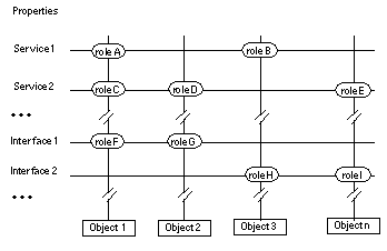
The notion of roles will help to satisfy both these requirements. We will use roles to represent objects (anonymously) in property models, and we may compose the properties of an object from roles described in different property models. The ovals in Figure 5-19 and Figure 5-20 represent roles.
- Service and interface properties related to objects
- Open figure
Several strands of thought pointed towards roles as a useful idea:
- That so much seem to depend on the point of view. Every object will have a relative view on other objects in its environment. Even system quality is relative. System quality can be formulated as the ability to play interface roles.
- That roles often are attached to associations (or relationships), e.g. the father - daughter roles. Such roles are important to describe and to understand.
- That there is some symmetry among the roles to be played at two sides of an interface.
- That it should be possible to characterise object behaviour in a purely external way, removing all irrelevant internal detail.
- That it should be possible to use such external characterizations to simplify validation of interconnections. A kind of plug-and-socket check that is (relatively) easy to perform, so that we can routinely ascertain that objects are only instantiated in environments where they will work properly.
- That validation effort, like development effort, should be modularized. It should be possible to focus validation and verification effort on types in a manner that simplifies validation of instances.
Categories of roles
The word "role" is used quite frequently in everyday life. The meaning is mostly informal, but will often be synonymous with a function or a relationship.
In a play, like Peer Gynt by Ibsen, we find roles such as Peer and Mor Aase. In the theatre, during a performance we find actors playing Peer and Mor Aase. The roles, as described by Ibsen, specify required properties of the actors without specifying what other properties they may have. If the actors are good, they provide the properties in a way that make us believe that Peer and Mor Aase are real. After the play is over, the actors will do something else and provide other properties. This notion of a role can be formalized as the properties of an object appearing in the context of a service (or function), the play.
Another notion of role comes from the relationship between objects. A person has the role of father in relation to his daughter, husband in relation to his wife and owner in relation to his car. This notion of role can be formalized as properties of an object appearing in relation to another object. It is typical for this kind of roles that they are related in pairs. The role of daughter is complemented by the role of father. It is also typical that the role correspond to required properties the actor should provide in that relationship. An object may well play many roles, but they should not be mixed. (Some reactions are bound to surface if a person mixes the role of husband with the role of father, for instance).
In general, every object provide some roles at its interfaces, and require complementary roles from the objects at the other side of the interface.
We will use two main categories of roles:
- Service roles, which are the observable behaviour of an object in a given service;
- Interface roles, which are the observable behaviour of an object at a given interface;
- Environment roles, which are the observable behaviour expected from an object in the environment of another object. Environment roles may be composed from interface roles and service roles.
Service roles
Service roles are the parts that objects play in a given service (or function) In a basic telephone call for instance, there is an initiating subscriber role, and a terminating subscriber role. These roles must be played by different objects in the same call (service invocation), but an object may well play both roles in different calls. Service roles are often dynamically assigned so that objects take on one service role at the time (but not always).
Interface roles
Interface roles allows us to describe and study (required and provided) properties at a particular interface, such as a user interface, and to discard the other interfaces. Using interface roles, we may describe and analyse the properties of each interface separately. In that way we obtain an external view structured according to the interfaces, e.g. the users view and the operators view. Interface roles are statically associated with the interfaces of an object (or system).
An object will often be able to perform several service roles and some of these may be accessible from the same interface as indicated in Figure 5-21.
- Service roles, interface roles and MSC
- Open figure
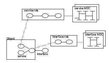
A service may also span several interfaces. Service roles may in special cases, be identical to interface roles, but more often several service roles will be visible in the same interface.
In relation to a given object structure, service roles observe the structure from "above", while interface roles observe it from "the side" through interfaces.
Environment roles
Each object type defines roles for entities in its environment, either explicitly or implicitly.
In TIMe we recommend to define the environment of each object type in the context part of the object model, and here we shall describe all the objects that are in the environment and somehow are related to instances of the type being defined.
Entities in the type environment are not real objects but rather anonymous objects that will become real objects when the type is instantiated. We consider these as environment roles.
For each instance of the type, every environment role shall be assigned to an actor, i.e. an object in the instance environment playing the role. For a system to be consistent, the play of all these roles must be valid. (Exactly what this means will be elaborated later.)
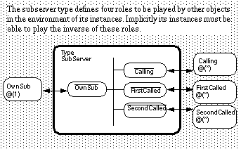
Thus, attached to an object type there are environment roles describing properties required from other objects. Due to symmetry, these implicitly describe properties provided by the object type as well see Figure 5-22.
- PBX Example: SubServer
- Open figure
Roles are projections
Interfaces and service roles are related to object designs by projection. These projections are similar to the well known geometrical projections in that they show everything that is visible from a given angle, and hides the rest. As in geometry we use projections in two ways:
- we synthesize new objects from projections, like a carpenter builds a house from a set of blueprints;
- we make projections of existing objects, in order to document and analyse their properties.
Both ways will be part of TIMe.
Instead of projections as geometrical views, we look at the observable behaviour of objects. When making such projections we can perform some consistency checks which are explained in Risk index.
To read more
For more about roles, see The relationship between objects and properties.
To read more about property modelling in general, see Property Modelling.
Describing functional properties
We shall use MSC as the main language to describe role behaviours.
Interface properties and service properties are described using:
- object diagrams describing the roles involved;
- signal lists for the connections;
- textual explanations;
- MSC for the interaction behaviour;
- data models for any data involved if needed..
As interfaces and services often will be layered, the property descriptions will be layered too.
The relationship between objects and properties
It is not obvious that a property description is consistent with an object design. Therefore, our first issue is to understand the relationship between object design descriptions and property descriptions. We are seeking principles that helps to:
- synthesize a consistent object design from specifications;
- extract and describe properties in a way faithful to the design;
- check consistency between object models and property models;
- perform verification and validation based on described properties (assuming that this will be simpler than to use derived properties).
The notion of roles is a key to all this.
The role-play principle
Through the environment roles of a type (defined in the context part of the type model) we formalise the requirements that instances of the type have on their environment.
When we use instances of the type in composition, see Figure 5-18, actual objects in their (instance) environment will be assigned the environment roles, and will have to play these roles as expected. Otherwise the composition will not be valid. Conversely, each of these actor objects assign roles the other way. In that way each object in a composition will assign environment roles to other objects and be assigned roles from them.
This role-play principle is symmetric. The validation of an interface is to check that both sides play the roles they mutually require from each other. It follows from these considerations that the notions of roles and plays are closely connected to the notion of validation and thus to system quality. If we are able to formalize these notions, we might find better ways to achieve quality control. This is one of the ideas we will pursue in TIMe.
Synthesizing a consistent object behaviour
The notion of Risk index can also be used constructively. Whenever we design a new process type we should ensure that it has a low risk index in all its roles.
Using environment roles
Environment roles may be used in several ways:
- to check the internal consistency of a behaviour. This can be done for a type independently of any particular application;
- to verify that the behaviour of an instance satisfies the requirements of the environment. This is done by checking offered roles against required roles (plug, socket);
- to represent behaviour in a way that simplify validation of interfaces;
- to derive (synthesize) object behaviours that are correct by construction.
We summaries with the following rule:
Role behaviour
- Define the behaviour of each role in the system and in the environment. Use the roles as basis for behaviour synthesis and validation.
Synthesising design
Two basic techniques are used to synthesise a design:
- Transformation. A source description is transformed to a target description according to well defined rules. One example is to generate code from an SDL design.
- Composition. The content is decomposed into parts (top down) and/or composed from parts (bottom up) using a mixture of manual and automated techniques. The method seeks to reuse existing types as much as possible, and to make new types that might be needed reusable. Thus, design with reuse and design for reuse is part of the method. Design with reuse involves:
- searching for existing types having some desired properties;
- adapting the properties to fit the particular application.
Composition
The content design is either a behaviour, or a (component) structure. In the case of a structure, each component type is synthesised using the same principle as for the enclosing type: first specify the context with properties and then synthesise the content. In this way, the make activities are invoked recursively, see Objects and Properties and Object models.
How should we proceed to synthesize the system structure from the requirements? We recommend the following core rules:
- Mirror the environment behaviour: The system structure should contain a concurrent actor for each concurrent role the environment requires from the system;
- Mirror the environment knowledge: The system structure should contain a data object for each entity or relation the system needs to know about. Allocate these data objects to the concurrent actor objects needing the knowledge, or to separate objects when the knowledge needs to be shared.
A precondition for the first rule is that we know the concurrent roles required by the environment. In other words: we are looking for environment roles that are to be composed in parallel. What kind of roles are that?
"Parallel composition will be the main rule for fragments on interfaces between different object pairs".
Therefore we need to identify the objects in the environment and the corresponding environment roles in order to see the concurrency required. Since our goal is to design a structure of objects and interfaces that will satisfy the requirements of the environment, it is hardly surprising that we have to start by identifying objects in the environment. By defining a type for each of them, we find the environment roles that the system shall play.
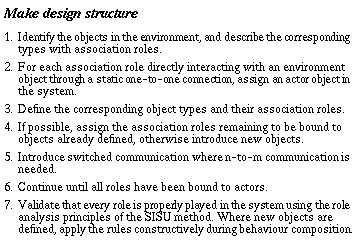
The following approach may be used when making a design structure.
If we have expressed the functional requirements entirely in terms of service role models, the first step will be to compose the service roles into environment roles.
We will use a PBX to illustrate the approach. In a PBX we usually identified a number of service roles called A-party, B-party, C-party, NormalCall, ConferenceCall, TransferCall, and so on.
Without any knowledge of the object structure, we cannot tell whether these roles should be composed in sequence or in parallel. When we know the objects, however, we may analyse the concurrency and determine how the roles shall be composed. For environment roles, such as the SubServer, we have this knowledge.
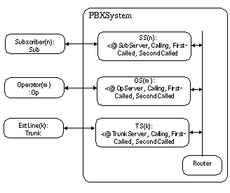
We therefore start with the environment and the environment roles it imposes on the system, see Figure 5-23
- Environment roles to be played by the PBX system
- Open figure
-
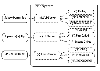
Each subscriber, being an instance of the TYPE Sub, demands that the system is able to play the role SubServer to serve their needs. We assume that corresponding roles, OpServer and TrunkServer, have been defined for the Op and the Trunk types. Since the subscribers are concurrent objects, their initiatives will be independent. The corresponding roles must therefore be composed in parallel. Since the sequence following each initiative is largely independent of other initiatives, the parallel composition is best achieved by concurrent objects as illustrated in Figure 5-23. At this point we may note the following:
The environment roles defined for the environment types are explicit representations of the needs of the environment!
The task of the designer is to find objects in the system that will satisfy these needs. When the needs are represented in the form of environment roles, this task is simplified a great deal. By using the environment mirroring principle, we easily get the first ideas about the object structure in the system. As a first step we identify an object for each of the statically assigned, concurrent roles in Figure 5-23, with the result shown in Figure 5-24.
- First object structure
- Open figure
-
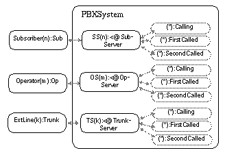
Our next step is to find actors for the remaining interface roles: Calling, FirstCalled and SecondCalled. Our first choice is always to look for actors among the existing objects. If they are not suitable actors, we introduce new objects. In this case it is specified that the actors shall represent instances of Sub, Op or Trunk observing the same role behaviour. We already have such objects both in the environment and in the system. In the environment we have direct instances of the specified actor types, and in the system we have the SS, OS and TS objects which may represent the same types. Using the internal representatives allows us to maintain a single, non-switched, channel towards each object in the environment. This will be our first choice, as indicated in Figure 5-25.
- Second object structure
- Open figure
-
These objects will not be totally independent and need to be coordinated. How can we know that? It follows clearly from the interface roles. The implications are the following:
- There must be communication paths in the system enabling each object playing SubServer to communicate with each of the possible actors of Calling, FirstCalled and SecondCalled.
- The roles FirstCalled and SecondCalled are dynamically assigned to actors.
- As a consequence we need switched communication paths in the system (This is hardly surprising, since we are designing a switching system, but the reader should note that we are able to deduce this formally from the static role structure without knowing anything about PBXs!)
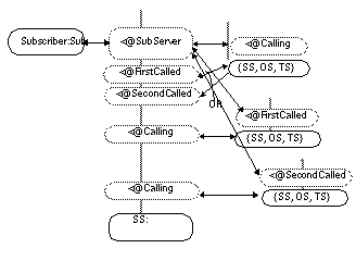
In order to design the types for the internal objects in the system, we apply the mirror principle again. Let us consider one of the SS objects. From the Subscriber, the SS object gets the SubServer role statically assigned. This role implies that the roles Calling, FirstCalled and SecondCalled are played by other objects in the system. These objects will in turn require corresponding roles to be played by the SS object, as illustrated in Figure 5-26.
- Roles that may be assigned to an SS object
- Open figure
-
Our next step is to define a type that will play these roles.We may do this in two ways:
- Reuse. The required roles are used as keys in a library search to find existing types with the ability to play the roles.
- New design. The role behaviours are used to compose a new type.
Both ways we must be aware of the how the roles should be composed (in sequence or in parallel). Analysing the initiatives, we see that the Calling role behaviours are triggered by a call initiative from the "own" subscriber, whereas the termination initiatives may come from either the "own" subscriber or some other object. The FirstCalled and SecondCalled role behaviours are triggered by initiatives taken by other system objects, whereas the termination may come from either those objects or the "own" subscriber. Consequently a combination of sequential and parallel composition is needed. It is not obvious which solution will be best in this case:
- having one sequential behaviour taking care of the parallel composition by branches (interleaving);
- having one object, e.g. one SDL service for each role.
If the second alternative is chosen, the dependencies must be taken care of by means of signals and/or shared data.